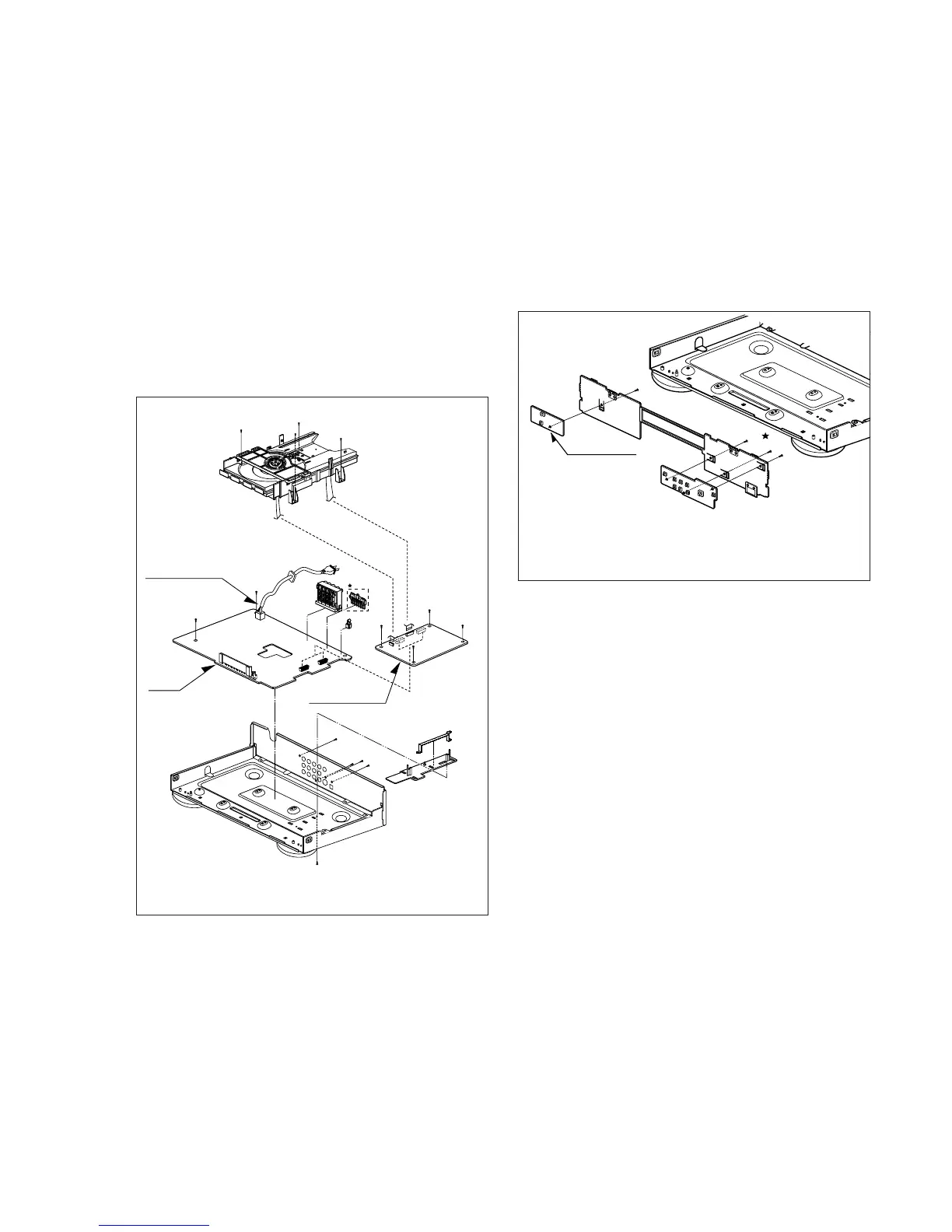
7.2 CIRCUIT BOARD DISASSEMBLY
Note: Before removing the main circuit board, be sure to shortcircuit the laserdiode output land.
After replacing the main circuit board, open the land after inserting the flexible connector.
(Refer to Mechanism Disassembly)
7.2.1 Disassembling of Main Circuit Board and Interface
Board
1. Remove the top case.(See Fig. 2-1)
2. Remove 12 screw (C).
3. Remove the deck from Main Circuit Board.
4. Remove Main Circuit Board from Interface Board.
5. Remove 2 screw (D).
6. Remove Interface Board from the chassis.
Fig. 2-4
7.2.2 Key Circuit Board
1. Remove the front panel.(See Fig. 2-3)
2. Release 4 screws (E), and remove the Key circuit board.
Main Circuit Board
(C)
(C)
(C)
(C)
(C)
(C)
(C)
(C)
(C)
(C)
(C)
(C)
Power Code
Interface
Board
(D)
(D)
Scart
Fig. 2-5