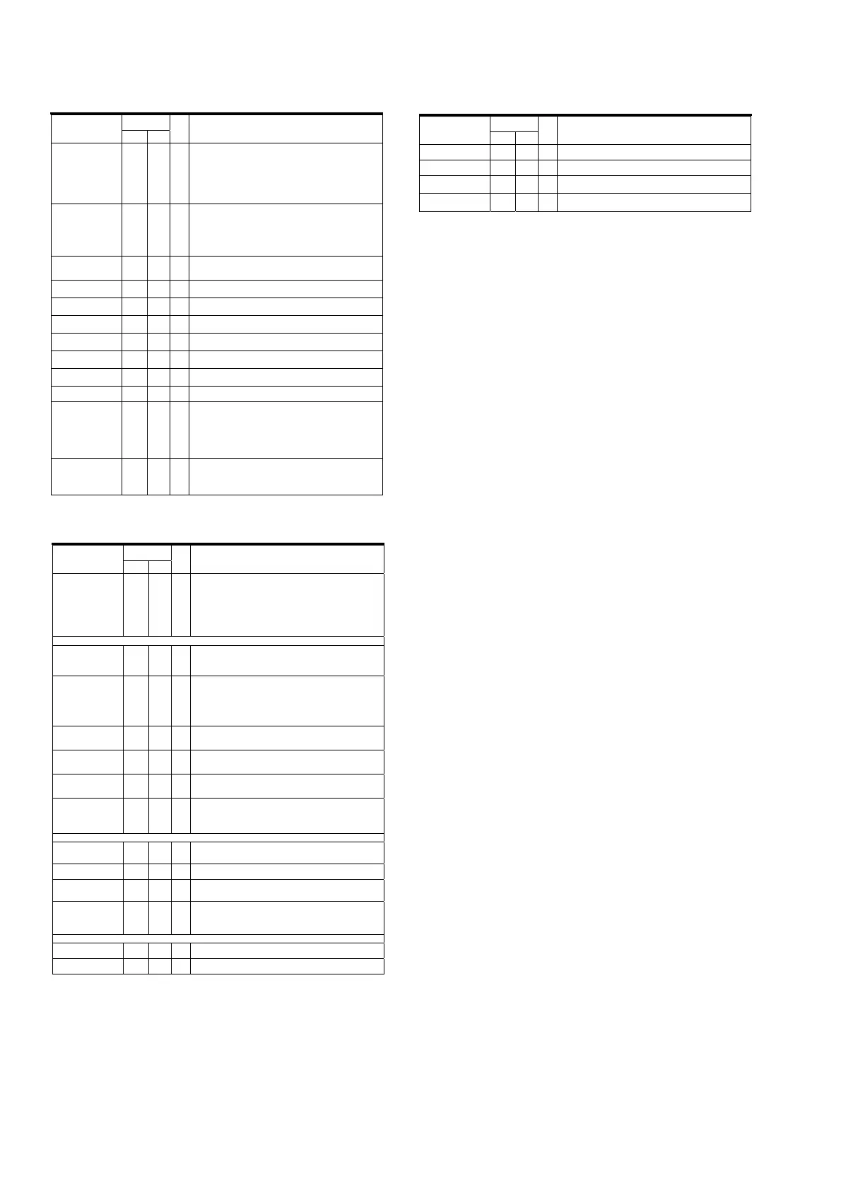
Terminal
Number
Terminal Name
BGA QFP
I/O Description
HSDI1_AVz C9 155 O
HSDI port 1 available. Programmable. Default active low.
For receive from 1394, this signal indicates if a 1394 packet is available in
the receive buffer for reading. The HSDI_AV signal for MPEG2 data also
depends on time stamp based release.
For transmit to 1394, this signal indicates the buffer level in HSDI TX
modes 8 and 9 by programming a CFR.
This pin indicates buffer level in transmit mode by programming a CFR. If
the buffer level is above a programmed level, HSDI_AV is asserted.
HSDI1_CLKz A9 153 I/O
HSDI port 1 clock. Programmable. Default rising edge sample. This clock
is used to operate the HSDI port 1 logic. In parallel mode, the maximum
clock is 27 MHz. In serial mode, the maximum clock is 70 MHz.
This signal is used as HSDI1_SACD_BCLK for SACD transmit and
receive.
MLPCM interface, HSDI1 audio port, and HSDI1 video port share
IsoPathBuffer 1. Only one interface can access the buffer at a time.
HSDI1_D0 B8 158 I/O
HSDI port 1 data 0 pin. Data 0 is the least significant bit on the HSDI data
bus. In serial mode, only HSDI0_D0 is used.
This signal is used as HSDI1_SACD_D0 for SACD transmit and receive.
HSDI1_D1 D8 159 I/O
HSDI port 1 data 1 pin
This signal is used as HSDI1_SACD_D1 for SACD transmit and receive.
HSDI1_D2 C7 163 I/O
HSDI port 1 data 2 pin
This signal is used as HSDI1_SACD_D2 for SACD transmit and receive.
HSDI1_D3 D7 164 I/O
HSDI port 1 data 3 pin
This signal is used as HSDI1_SACD_D3 for SACD transmit and receive.
HSDI1_D4 A6 165 I/O
HSDI port 1 data 4 pin
This signal is used as HSDI1_SACD_D4 for SACD transmit and receive.
HSDI1_D5 B6 166 I/O
HSDI port 1 data 5 pin
This signal is used as HSDI1_SACD_D5 for SACD transmit and receive.
HSDI1_D6 C6 167 I/O
HSDI port 1 data 6 pin
This signal is used as HSDI1_SACD_A for SACD transmit and receive.
HSDI1_D7 A5 168 I/O
HSDI port 1 data 7 pin. Data 0 is the most significant bit on the HSDI
data bus.
HSDI1_DVALIDz A8 157 I/O
HSDI port 1 data valid pin. Programmable. Default active high. This pin
indicates if data on the HSDI data bus valid for reading or writing.
For transmit to 1394, this signal is provided by the system with the data.
For receive from 1394, iceLynx-Micro provides this signal with the data.
For HSDI DV modes, this signal is used as HSDI0_FrameSync indicating
DV frame boundary.
If not used in transmit mode, this signal is pulled low.
HSDI1_ENz D9 154 I
HSDI port 1 enable. Programmable. Default active low. Input by the
system to enable the HSDI for both transmit to and receive from 1394.
If not used, this signal is pulled enabled (low or high depending on the
polarity set). The application can use HSDI_DVALID or HSDI_SYNC to
validate the HSDI data.
Terminal
Number
Terminal Name
BGA QFP
I/O Description
HSDI1_SYNCz B9 156 I/O
HSDI port 1 sync signal. Programmable. Default active high. This signal
indicates the start of a packet.
For transmit to 1394, this signal is provided by the system with the data.
For receive from 1394, iceLynx-Micro provides this signal with the data.
If not used in transmit mode, this signal is pulled low or high depending on
the polarity.
This signal is used as HSDI1_SACD_FRAME for SACD transmit and
receive.
DVD-Audio Interface Pins
MLPCM_A G3 14 I/O
Audio MLPCM interface ancillary data. Ancillary data is input/output using
this pin. For DVD-Audio, MLPCM_LRCLK determines if ancillary left or
ancillary right data is present.
This signal also functions as FLWCTL_A in flow control mode.
MLPCM_BCLK E1 9 I/O
Audio MLPCM interface bit clock. Multiple functions:
DVD audio BCK (I)
DVD audio BCK (O)
Flow control BCK (I/O)
MLPCM interface, HSDI1 audio port, and HSDI1 video port share
IsoPathBuffer 1. Only one interface can access the buffer at a time.
MLPCM_D0 F2 11 I/O
Audio MLPCM interface D0. Contains channel 1 and channel 2
information. MLPCM_LRCLK determines which channel is present.
This signal also functions as FLWCTL_D0 in flow control mode.
MLPCM_D1 F1 12 I/O
Audio MLPCM interface D1. Contains channel 3 and channel 4
information. MLPCM_LRCLK determines which channel is present.
This signal also functions as FLWCTL_D0 in flow control mode.
MLPCM_D2 G4 13 I/O
Audio MLPCM interface D2. Contains channel 5 and channel 6
information. MLPCM_LRCLK determines which channel is present.
This signal also functions as FLWCTL_D0 in flow control mode
MLPCM_LRCLK F3 10 I/O
Audio MLPCM interface left-right clock. Multiple functions:
DVD audio LRCLK (I)
DVD audio LRCLK (O)
Flow control LRCLK (I/O)
Audio Phase Lock Loops Pins
DIV_VCO E3 7 O
Output for external phase detector. This signal is the divided VCO_CLK. It
used by the external phase detector to compare with the REF_SYT signal.
The divide ratios are setup in CFR.
PLL_TEST E2 8 O
PLL test. This signal is used for internal Texas Instruments testing and
must be unconnected for normal operation.
REF_SYT D1 6 O
Output for external phase detector. This signal represents the SYT match
for received audio or DV packets. The phase detector uses it as input to
detect differences between the SYT match and the VCO clock.
VCO_CLK D2 5 I
Input from VCO. This signal generates internal audio and DV clocks for
receive clock recovery.
Audio frequency: 33.868 MHz or 36.864 MHz.
DV frequency: 30.72 MHz, 27 MHz
Test Mode Pins
TEST_MODE0 C2 2 I/O
Test mode. Used for internal Texas Instruments testing. Must be pulled
low for normal operation.
TEST_MODE1 C1 3 I/O
Test mode. Used for internal Texas Instruments testing. Must be pulled
low for normal operation.
Terminal
Number
Terminal Name
BGA QFP
I/O Description
TEST_MODE2 P7 57 I/O
Test mode. Used for internal Texas Instruments testing. Must be pulled
low for normal operation.
TEST_MODE3 R7 58 I/O
Test mode. Used for internal Texas Instruments testing. Must be pulled
low for normal operation.
TEST4 R9 67 I/O
Factory test pin. Must tie to low for normal operation.
Recommend connection to ground through a 1-k: resistor.
TEST5 T9 68 I/O
Factory test pin. Must tie to low for normal operation.
Recommend connection to ground through a 1-k: resistor.
[PI01] QI01 : TSB43CA42PGF
172