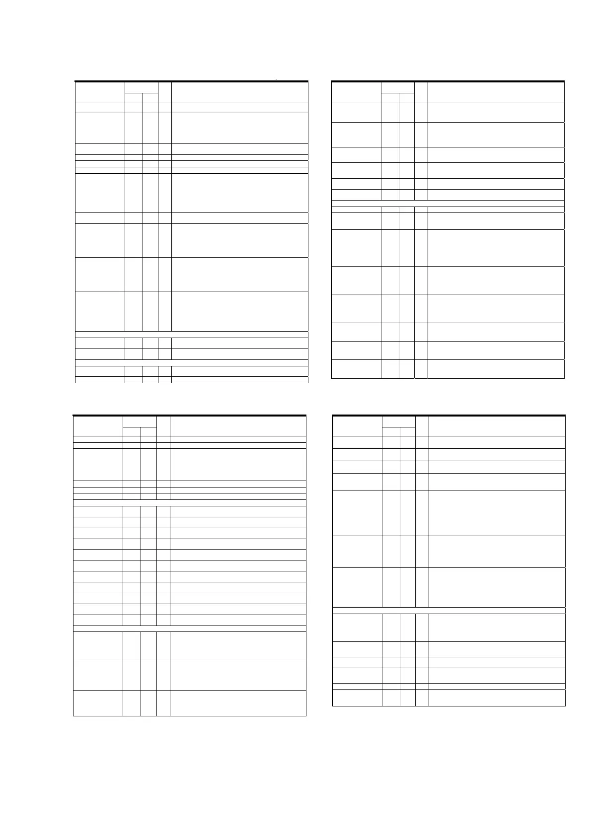
[PI01] QI01 : TSB43CA42PGF
Terminal
Number
Terminal Name
BGA QFP
I/O Description
MCIF_DATA15 G15 119 I/O
MCIF data 15 pin. This data pin is the most significant bit of the MCIF
data bus.
MCIF_ENDIAN B17 132 I
MCIF endian pin. This sets the endianness for accesses between the
external CPU and the internal iceLynx-Micro memory. This pin sets
endianness for all MCIF modes. When set to 0, data is read/written to the
ex-CPU exactly as it is stored in iceLynx-Micro memory. (Big endian)
When set to 1, data is swapped on half-word and byte boundaries before it
is read/written to the ex-CPU. (Little endian)
MCIF_INTz T17 89 O
MCIF Interrupt. This signal is push-pull (always asserted). It does not
require a pullup resistor.
MCIF_MODE0 A16 133 I MCIF mode 0. Used to select MCIF mode.
MCIF_MODE1 B15 134 I MCIF mode 1. Used to select MCIF mode.
MCIF_MODE2 A15 135 I MCIF mode 2. Used to select MCIF mode.
MCIF_OEz N16 96 I
MCIF output enable. Default active low. This input pin indicates if the
system CPU wants to perform a MCIF read access. This signal is used for
the following modes:
SH-3 I/O access
M16C/62 I/O access
Memory access
This signal must be pulled high if not used.
MCIF_R_nWz P15 92 I
MCIF read/write pin. Default value for a read is 1. Default value for a write
is 0.
MCIF_STRBz P16 93 I
MCIF strobe pin. Default active low. This pin is used (along with
MCIF_CS_IOz) to validate the MCIF access. This signal is used for the
following modes:
68000 + wait I/O access
MPC850 I/O access
When not used, this pin must be pulled high.
MCIF_WAITz P17 94 O
MCIF wait pin. Default active high. iceLynx-Micro asserts this signal if it is
not ready to service an MCIF request. When not asserted, this signal is in
a high-Z state. This signal is used for the following modes:
68000 + wait I/O access
SH-3 I/O access
M16C/62 I/O access
MCIF_WEz N17 97 I
MCIF Write Enable. Default active low. This input pin indicates if the
system CPU wants to perform a MCIF write access. This signal is used for
the following modes:
x SH-3 I/O access
x M16C/62 I/O access
x Memory access
This signal must be pulled high if not used.
Universal Asynchronous Receiver Transmitter Pins
UART_RxD U15 86 I
UART receive port. Data from the system is input to the UART buffer
using this pin.
UART_TxD R14 85 O
UART transmit port. Data from the UART buffer is output to the system
using this pin.
Joint Test Action Group (JTAG) and ARM Pins
JTAG_TCK U13 80 I
JTAG clock pin. Both the boundary scan and ARM JTAG uses this input
for the JTAG clock.
JTAG_TDI T12 78 I JTAG test data input pin
Terminal
Number
Terminal Name
BGA QFP
I/O Description
JTAG_TDO R12 79 O JTAG test data output pin
JTAG_TMS U12 77 I JTAG test mode selector pin
JTAG_TRSTn T13 81 I
JTAG reset pin. Both the boundary scan and ARM JTAG uses this input
for the JTAG clock.
Note 1: TSB43Cx43A/TSB43CA42 must have JTAG_TRSTn=0 for correct
ARM interrupt operation.
Note 2: JTAG_TRST must be asserted once after power-up for correct
operation of the iceLynx-Micro.
ARM_TDI U14 83 I ARM JTAG test data input pin
ARM_TDO T14 84 O ARM JTAG test data output pin
ARM_TMS R13 82 I ARM JTAG test mode selector pin
General-Purpose Input/Out Pins (GPIO)
GPIO0 U9 65 I/O
GPIO0. Can be programmed as general-purpose input, general-purpose
output, or specific function. Power-up default is input.
GPIO1 P9 66 I/O
GPIO1. Can be programmed as general-purpose input, general-purpose
output, or specific function. Power-up default is input.
GPIO2 G2 15 I/O
GPIO2. Can be programmed as general-purpose input, general-purpose
output, or specific function. Power-up default is input.
GPIO3 G1 16 I/O
GPIO3. Can be programmed as general-purpose input, general-purpose
output, or specific function. Power-up default is input.
GPIO4 H1 17 I/O
GPIO 4. Can be programmed as general-purpose input, general-purpose
output, or specific function. Power-up default is input.
GPIO5 H4 18 I/O
GPIO 5. Can be programmed as general-purpose input, general-purpose
output, or specific function. Power-up default is input.
GPIO6 U10 69 I/O
GPIO6. Can be programmed as general-purpose input, general-purpose
output, or specific function. Power-up default is input.
GPIO7 T10 70 I/O
GPIO7. Can be programmed as general-purpose input, general-purpose
output, or specific function. Power-up default is input.
GPIO8 P10 71 I/O
GPIO8. Can be programmed as general-purpose input, general-purpose
output, or specific function. Power-up default is input.
GPIO9 R10 72 I/O
GPIO9. Can be programmed as general-purpose input, general-purpose
output, or specific function. Power-up default is input.
GPIO10 T15 87 I/O
GPIO10. Can be programmed as general-purpose input, general-purpose
output, or specific function. Power-up default is input.
Physical Layer Pins
TPA0_N
TPA1_N
TPA2_N
TPA0_P
TPA1_P
TPA2_P
L1,
N1,
R1,
L2,
N2, R2
29,
36,
42,
30,
37,
43
I/O
Twisted pair A differential signal terminals. For an unused port, TPAN and
TPAP signals are left open (i.e., TSB43CA42 for Port 2).
TPB0_N
TPB1_N
TPB2_N
TPB0_P
TPB1_P
TPB2_P
K1,
M1,
P1,
K2,
M2,
P2
25,
33,
39,
26,
34,
40
I/O
Twisted pair B differential signal terminals. For an unused port, TPBN and
TPBP signals are left open (i.e., TSB43CA42 for Port 2).
TPBIAS0
TPBIAS1
TPBIAS2
L3,
N3, T1
31,
38,
44
I/O
Twisted pair bias output. These signals provide the 1.86-V nominal bias
voltage needed for proper operation of the twisted pair driver and
receivers for signaling an active connection to a remote node.
For an unused port, TPBIAS is left unconnected (i.e., TSB43CA42 for
Port 2).
Terminal
Number
Terminal Name
BGA QFP
I/O Description
R1
R0
T3, U3
46,
47
-
Current setting resistors. These pins are connected to external resistors to
set the internal operating currents and cable driver output currents. A
resistance of 6.34 k:r 1% is required to meet the IEEE 1394-1995 output
voltage limits.
FILTER0
FILTER1
T4, U4
49,
50
I/O
PLL filter terminals. These terminals are connected to an external
capacitor to form a lag-lead filter required for stable operation of the
internal frequency-multiplier PLL, which is using the crystal oscillator. A
0.1-PF r10% capacitor is the only external component required to
complete this filter.
XI
X0
T5, U5
52,
53
-
Crystal oscillator inputs. These terminals connect to a 24.576-MHz parallel
resonant fundamental mode crystal. The optimum values for the external
shunt capacitors are dependent on the crystal used.
CPS J4 22 I
Cable power status. This input to iceLynx-Micro detects if cable power is
present. This pin must be connected to the cable power through 390-k:
resistor.
MSPCTL H3 19 I
Maximum speed of PHY. When this signal is high; S100 and S200
operation. When this signal is low; S100, S200, and S400 operation.
LINKON U8 61 O
Link-on output. This signal is asserted whenever LPS is low and a link-on
packet is received from the 1394 bus.
High Speed Data Interface (HSDI) Port 0 Pins
HSDI0_60958_IN C14 136 I 60958 data input
HSDI0_AMCLK_IN B14 137 I
Audio master clock input. This clock is used to decode the bi-phase
encoding of 60958 data.
This pin is also used to input the 1.5 x BCLK for flow control mode.
HSDI0_AVz B13 140 O
HSDI port 0 available. Programmable. Default active low.
For receive from 1394, this signal indicates if a 1394 packet is available in
the receive buffer for reading. The HSDI_AV signal for MPEG2 data also
depends on time stamp based release.
For transmit to 1394, this signal indicates buffer level in HSDI TX modes 8
and 9 by programming a CFR. If the buffer level is above a programmed
level, HSDI_AV will be asserted.
HSDI0_CLKz A14 138 I
HSDI port 0 clock. Programmable. Default rising edge sample. This clock
is used to operate the HSDI port 0 logic. In parallel mode the maximum
clock is 27 MHz. in serial mode, the maximum clock is 70 MHz.
This signal is output to HSDI1_CLKz in pass-through mode.
This signal is used as HSDI0_MLPCM_BCLK for DVD-audio transmit.
HSDI0_D0 B12 143 I/O
HSDI port 0 data 0 pin. Data 0 is the least significant bit on the HSDI data
bus.
In serial mode, only HSDI0_D0 is used.
This signal is output to HSDI1_D0 in pass-through mode.
This signal is used as HSDI0_MLPCM_D0 for DVD-audio transmit.
HSDI0_D1 A12 144 I/O
HSDI port 0 Data 1 pin
This signal is output to HSDI1_D1 in pass-through mode.
This signal is used as HSDI0_MLPCM_D1 for DVD-audio transmit.
HSDI0_D2 B11 147 I/O
HSDI port 0 Data 2 pin
This signal is output to HSDI1_D2 in pass-through mode.
This signal is used as HSDI0_MLPCM_D2 for DVD-audio transmit.
HSDI0_D3 A11 148 I/O
HSDI port 0 Data 3 pin
This signal is output to HSDI1_D3 in pass-through mode.
This signal is used as HSDI0_MLPCM_A for DVD-audio transmit.
p
Terminal
Number
Terminal Name
BGA QFP
I/O Description
HSDI0_D4 A10 149 I/O
HSDI port 0 data 4 pin
This signal is output to HSDI1_D4 in pass-through mode.
HSDI0_D5 D10 150 I/O
HSDI port 0 data 5 pin
This signal is output to HSDI1_D5 in pass-through mode.
HSDI0_D6 C10 151 I/O
HSDI port 0 data 6 pin
This signal is output to HSDI1_D6 in pass-through mode.
HSDI0_D7 B10 152 I/O
HSDI port 0 data 7 pin. Data 0 is the most significant bit on the HSDI data
bus.
This signal is output to HSDI1_D7 in pass-through mode.
HSDI0_DVALIDz C12 142 I/O
HSDI port 0 data valid pin. Programmable. Default active high. This pin
indicates if data on the HSDI data bus valid for reading or writing.
For transmit to 1394, this signal is provided by the system with the data.
For receive from 1394, iceLynx-Micro provides this signal with the data.
For HSDI DV modes, this signal is used as HSDI0_FrameSync indicating
DV frame boundary.
This signal is output to HSDI1_DVALIDz in pass-through mode
If not used in transmit mode, this signal is pulled low.
HSDI0_ENz C13 139 I
HSDI port 0 enable. Programmable. Default active low. Input by the
system to enable the HSDI for both transmit to and receive from 1394.
If not used, this signal is pulled enabled (low or high depending on the
polarity set). The application can use HSDI_DVALID or HSDI_SYNC to
validate the HSDI data.
This signal is used as HSDI0_MLPCM_LRCLK for DVD-audio transmit.
HSDI0_SYNCz A13 141 I/O
HSDI port 0 sync signal. Programmable. Default active high. This signal
indicates the start of packet.
For transmit to 1394, this signal is provided by the system with the data.
For receive from 1394, iceLynx-Micro provides this signal with the data.
This signal is output to HSDI1_SYNCz in pass-through mode.
If not used in transmit mode, this signal is pulled low or high depending on
the polarity.
High Speed Data Interface (HSDI) Port 1 Pins
HSDI1_AMCLK_IN B5 169 I
Audio master clock input. This clock is used to decode the bi-phase
encoding of 60958 data.
This pin also inputs the 1.5 x BCK for flow control mode.
MLPCM interface, HSDI1 audio port, and HSDI1 video port share
IsoPathBuffer 1. Only one interface can access the buffer at a time.
HSDI1_AMCLK_OUT C5 170 O
Audio master clock output. This clock is derived from the VCO_CLK input.
60958 data output from iceLynx-Micro is bi-phase encoded using this
clock.
HSDI1_AUDIO_ERR A4 171 O
Audio error signal. iceLynx-Micro asserts this signal whenever an audio
error condition occurs. (Receive from 1394 only.)
HSDI1_AUDIO_MUTE B4 172 O
Audio mute status. iceLynx-Micro asserts this signal whenever an audio
mute condition has occurred, and hardware has muted the HSDI1 audio
interface. (Receive from 1394 only.)
HSDI1_60958_IN C4 173 I 60958 data input
HSDI1_60958_OUT A3 174 O
60958 data output
This signal is also used as FLWCTRL_DVALID in flow control data valid
mode.
171
 Loading...


