49
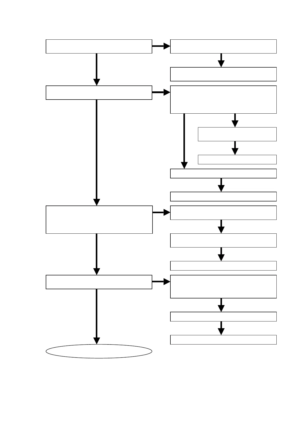
3.4 Check the DIGITAL VEDEO OUTPUT.
NG
OK
NG
OK
OK
NG OK
OK
NG
OK
OK
OK
OK
OK
NG
OK
OK
Are digital output signals of Q101 normal?
PXD(0-7), VCLK(27MHz)
Is the reset signal normal?
Q109 (9pin) = H
Is communication to QK01 of digital
signals normal?
Check that 13pin, 16pin, 3-10pin and 137pin.
Are the VD+3.3V and VD+1.8V voltage
lines of QK01 normal?
Refer to Video 2
Check the soldering of Q101 (183-192pin),
R201, R202 and R125.
Refer to “3.1 Check the panel
microprocessor”.
Check the 11pin on Q109.
(Change to H from L, after turn on the unit.)
Check 8pin on Q109 H?
Check the soldering of R189,
R190, R191 and Q108.
Replace Q108.
Check the soldering R192 and Q109.
Replace Q109.
Check the soldering of QK10, QK11 and
circumference components.
Check theVD+3.3V line and soldering of
LK34.
Replace QK10 or QK11.
Check the soldering of QK91, QK92 and
circumference components.
Check the soldering of LD01and LK02.
Check the E+4V voltage line.
Replace QK91 or QK92.