48
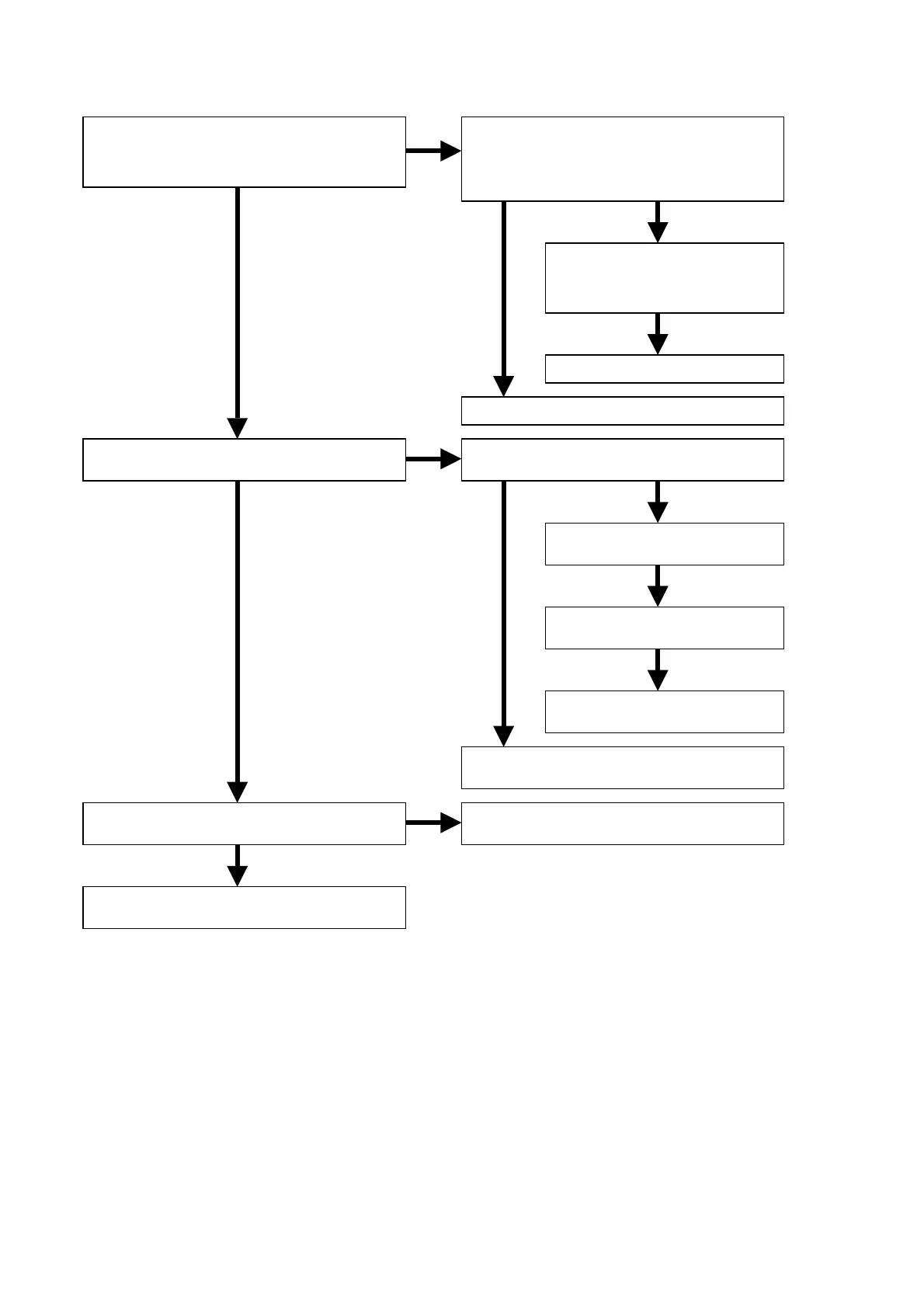
3.3 Check the F/E microprocessor.
NG OK
OK
NG OK
OK
OK
OK
Finish
OK
OK
NG
NG
NG
Are the +3.3V_D2, +1.8V_D2, +3.3V_A2
and +1.8V_A2, of Q502 voltage lines
normal?
Is the clock waveform of 33pin on Q502
normal? (33.87MHz. 2Vp-p)
Is the 51pin of Q502 H?
• Check the soldering of Q114, Q115, and
the input/output voltage.
• Check the soldering of L404, L407 and
circumference components.
Check the soldering of
the Q502 and circumference
components.
Replace Q114 or Q115.
Refer to “1. POWER SUPPLY PWB (P801)”.
Check the waveform of 15pin on Q105.
(33.87MHz 2Vp-p)
Check the waveform of 2pin
on Q111. (33.87MHz)
Check the waveform of 2pin
on Q405. (33.87MHz)
Check the soldering of R491
and R574.
Check the soldering of X101,
circumference components and Q105.
Check the soldering of Q102 (108pin),
R129, R570, R648 and C638.