61
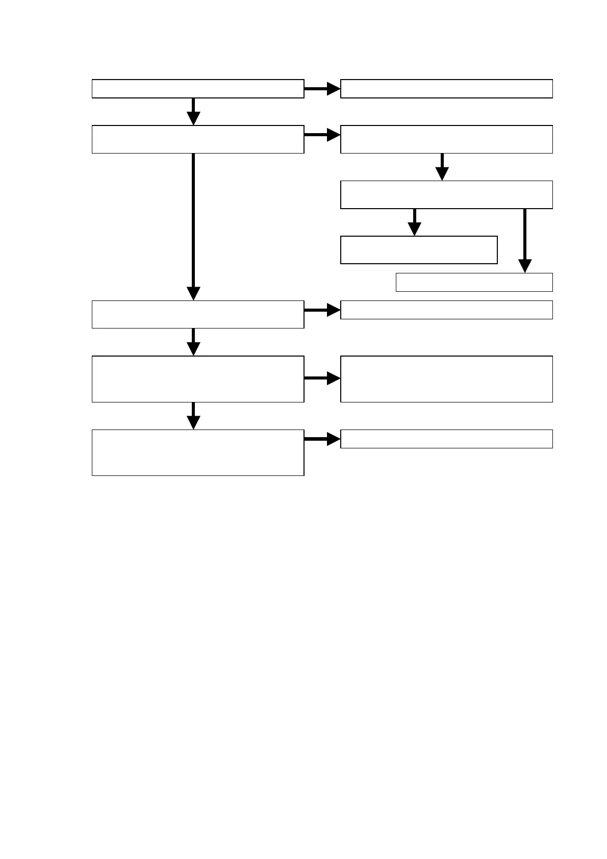
5.2 Picture is not outputted normally. (Com po nent)
NG
NG
OK
OK
NG OK
NG
OK
OK
NG
OK
NG
Is the E+6V voltage line of JV05 normal?
Is the +5VV voltage line of QY07 normal?
Are the video signals inputted to QY01 (Y),
QY03 (Cb) and QY05 (Cr)?
Are the video signals inputted to each pin
of QY07?
1pin=Y, 3pin=Cb, 5pin=Cr
Are the video signals outputted to each pin
of QY07?
9pin=Y, 11pin=Cb, 13pin=Cr
Refer to “POWER SUPPLY PWB (P801)”.
Check the output voltage of QV91.
+5V
Check the QV91 (1pin) level.
1pin=H
Refer to “3.1 Check the panel
microprocessor”.
Replace QV91.
Refer to “3.4 DIGITAL VEDEO OUTPUT”.
Check the soldering of video filter block.
Y=QY01-QY02, Cb=QY03-QY04,
Cr=QY05-QY06
Replace QY07.