63
6. AUDIO PWB (PV01)
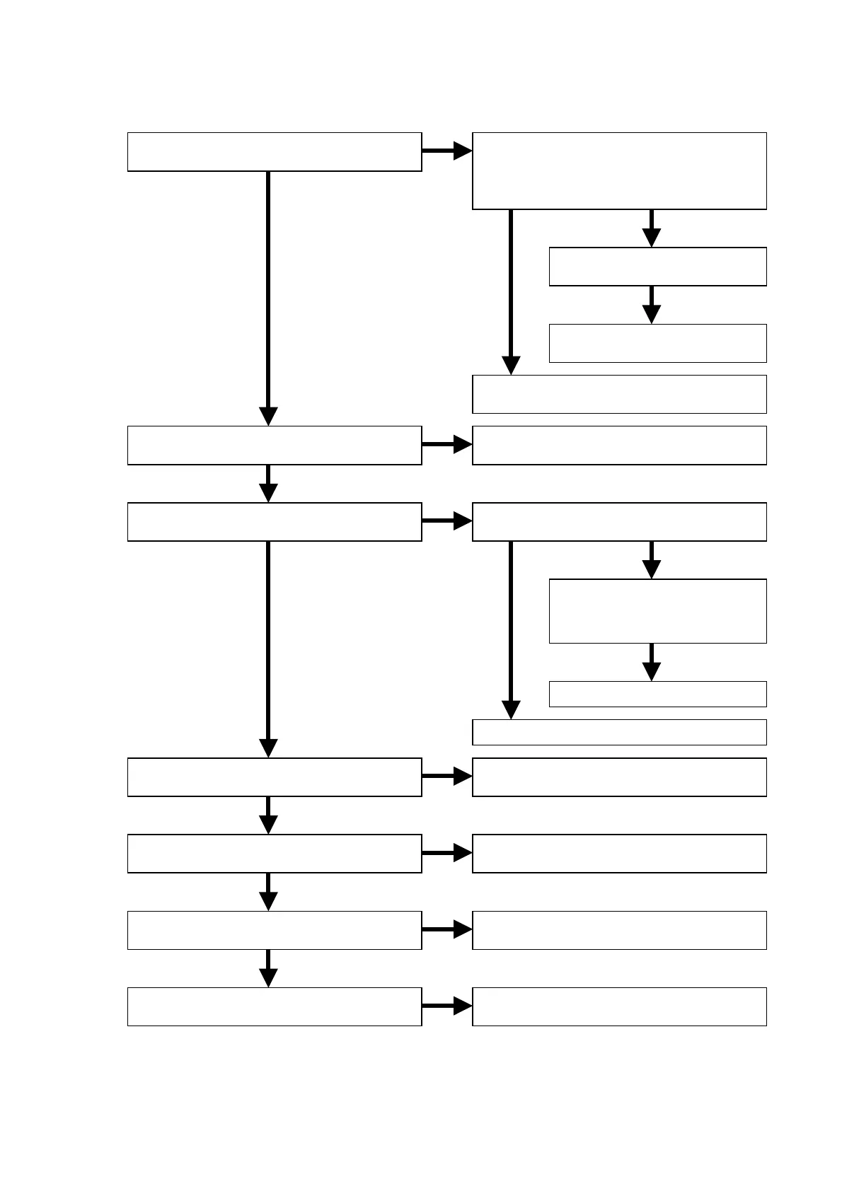
6.1 Audio is not outputted normally.
NG
OK
OK
OK
NG
OK
NG
OK
OK
NG
OK
NG
NG
OK
NG
NG
OK
NG
OK
Are the +3.3VDD and +5VDA voltage lines
of QD01, QD21 and QD41 normal?
Are the +8VA and -8VA voltage lines of
JA01 normal?
Is the MCLK signal of QD01, QD21 and
QD41 (6pin) normal?
Is the waveform of QD01, QD21 and
QD41 (3-5pin) normal?
Are the AOUTA+/- and AOUTB+/- signals
of QD01, QD21 and QD41 normal?
Are the MUTE signals of JD01 (4, 5pin)
normal?
Are the MUTE signals inputted/outputted
to each pin of the connected components?
Check the output voltage of J853 (3pin
and 6pin) on POWER SUPPLY PWB (P801),
afterthe wire between J853 and JA02
disconnected.
Check the soldering of QD01,
QD21 and QD41.
Replace QD01, QD21 or
QD41.
Check the power supply circuit of +5VA and
+3.3VD on POWER SUPPLY PWB (P801).
Check the power supply circuit of +8VA
and -8VA on POWER SUPPLY PWB (P801).
Check the input signals of QD61
(1pin and 2pin).
Check the soldering of QD61
and circumference components.
Replace QD61.
Check the MCLK signal of MAIN PWB (PM01).
Check the audio data output signal of
MAIN PWB (PM01).
Check the soldering of QD01, QD21
and QD41.
Check the MUTE output signal of
MAIN PWB (PM01).
Replace defect component.