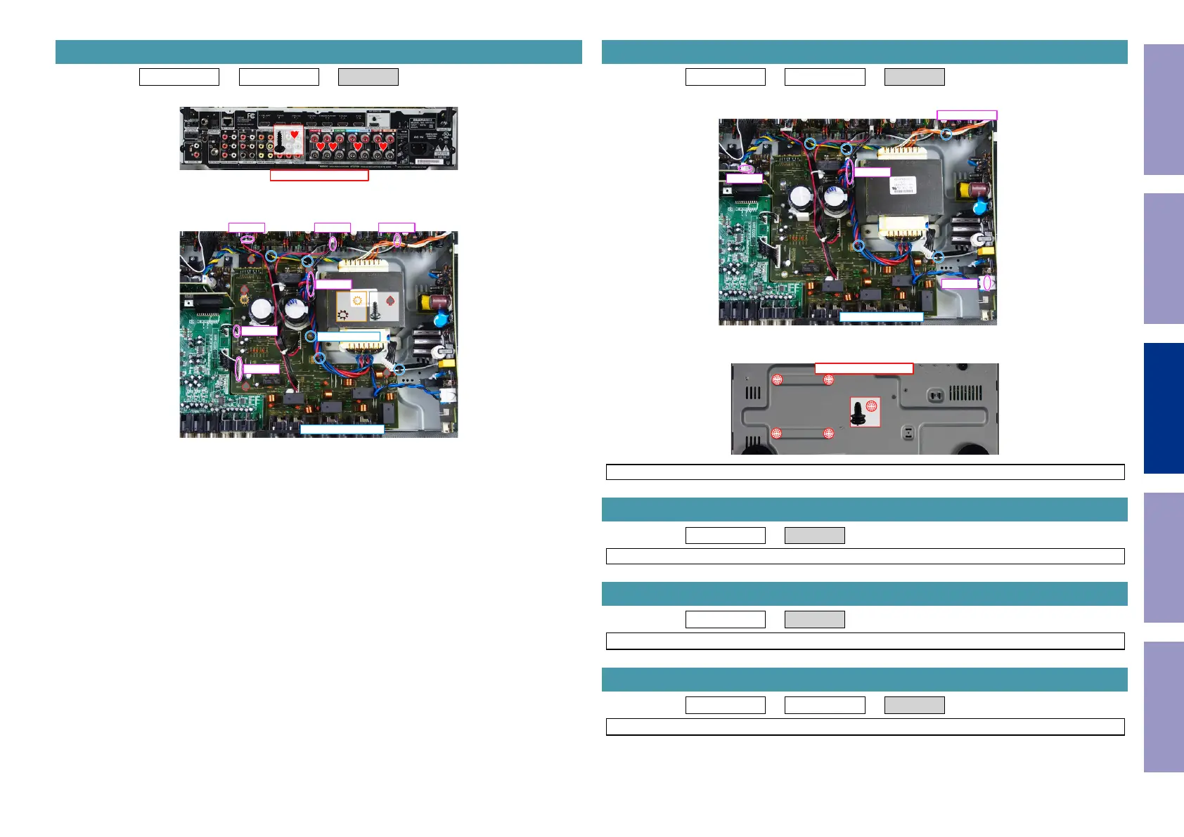
Proceeding : TOP COVER → DIGITAL PCB → SPK PCB
(1) Remove the screws.
(2) Remove the screws. Remove the CORD HOLDER and connectors. Remove the HOLDER.
4. SPK PCB
↑Shooting direction: A↑
x4
x1 x5
CP4002
CP4000
CP4001
CP4803CP4803CP4803
CORD HOLDER x4
PCB HOLDER
Proceeding : TOP COVER → DIGITAL PCB → TRANS
(1) Remove the CORD HOLDERs and connector wires.
(2) Remove the screws.
NOTE : It will separate and TRANS will fall from SET, if screws is removed.
Proceeding : TOP COVER → SMPS PCB
See "EXPLODED VIEW" for instructions on removing the SMPS PCB.
Proceeding : TOP COVER → REG PCB
See "EXPLODED VIEW" for instructions on removing the REG PCB.
Proceeding : TOP COVER → DIGITAL PCB → AV PCB
See "EXPLODED VIEW" for instructions on removing the AV PCB.
5. TRANS
CP4001
from CP4401
CP4607
CP4142
CORD HOLDER x5
View from the bottom
x4
6. SMPS PCB
7. REG PCB
8. AV PCB
Before Servicing
This Unit
Electrical Mechanical Repair Information Updating
71