EasyManua.ls Logo

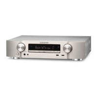
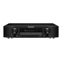
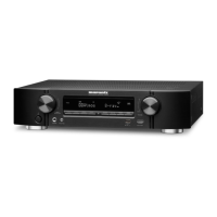
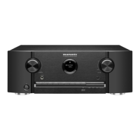
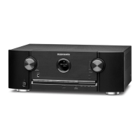
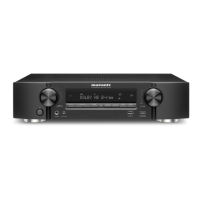
Marantz NR1506 /U1B User Manual

Marantz NR1506 /U1B
159 pages
To Next Page IconTo Next Page
Page #1 background imageLoading...
Page #1 background image
AV SURROUND RECEIVER
NR1506 /
U1B/N1B/N1SG/K1B
NR1506
S1214V03DM/DG1603
Copyright 2016 D&M Holdings Inc. All rights reserved.
WARNING: Violators will be prosecuted to the maximum extent possible.
Ver. 3
•
Some illustrations using in this service manual are slightly different from the actual set.
•
Please use this service manual with referring to the operating instructions without fail.
•
For purposes of improvement, specications and design are subject to change without notice.
Please refer to the
MODIFICATION NOTICE.
Service
Manual
Question and Answer IconNeed help?

Do you have a question about the Marantz NR1506 /U1B and is the answer not in the manual?

Marantz NR1506 /U1B Specifications

General IconGeneral
Channels5.1
Power Output50W per channel (8 ohms, 20Hz-20kHz, 0.08% THD)
HDMI Inputs6
HDMI Outputs1
Wi-FiYes
BluetoothYes
Dolby TrueHDYes
DTS-HD Master AudioYes
4K Ultra HD Pass-throughYes
HDCP SupportHDCP 2.2
AirPlayYes
Spotify ConnectYes
Internet RadioYes
Phono InputNo
Frequency Response10 Hz - 100 kHz
Total Harmonic Distortion0.08%
Input Sensitivity200 mV
Signal-to-Noise Ratio98 dB
Tuner TypeAM/FM
Ethernet PortYes
Dimensions17.3 x 4.1 x 12.9 inches
USB Port1

Summary

SAFETY PRECAUTIONS

Leakage Current Check Procedure

Procedure to check leakage current before returning the set.

General Servicing Cautions

Important instructions for servicing, including electric shock and disassembly.

Part Handling and Replacement Guidelines

Guidelines for using designated parts and arranging wires as originally placed.

Post-Servicing Safety Checks

Essential checks after servicing to ensure safety and insulation.

Important Safety Parts Identification

Identifies and emphasizes the importance of using designated safety parts.

Notes and Handling Instructions

Semi-conductor and Optical Unit Handling

Precautions for preventing electrostatic discharge during handling.

SPECIFICATIONS

Audio Section Specs

Details on power amplifier, output connectors, and analog audio input.

Wireless LAN and Bluetooth Specs

Details on wireless network standards and Bluetooth system.

CAUTION IN SERVICING

Initializing This Unit

Procedure to initialize the unit after component replacement.

SPECIAL MODE Operations

Special Mode Setting Button

Explains how to enter special modes using buttons.

Firmware Version Display Mode

Mode to display firmware versions and error codes.

Service-Related Modes

Modes for checking protection history, operation info, and tuner settings.

Initialization and Lock Modes

Modes for unit initialization, panel lock, and CY920 reboot.

Firmware Update Modes

Modes for USB and forced USB firmware updates.

Selecting Service-Related Operations Modes

Displaying and Selecting Each Mode

Shows how to display and select service modes like Service Path Check.

DIAGNOSTIC MODE (Service Path Check Mode)

Audio System Confirmation Items

Details for confirming audio paths and their settings.

Video System Confirmation Items

Video Paths and Settings Confirmation

Details for confirming video paths and their settings.

Protection History Display Mode

Protection Information Display

How to check and interpret protection history events.

Clearing Protection History

POWER LED Warning Displays

Operation Info Mode

Operations and Information Display

How to view accumulated operating time and protection counts.

Protection Pass Mode

CY920 Reboot Mode

CY920 Initialization Mode

Operations

Procedure for initializing the CY920 module, clearing settings.

POST-REPLACEMENT PROCEDURES

Microprocessor and Related Component Replacement

Steps for writing software after replacing key components.

FIRMWARE UPDATE PROCEDURE

1. Updating via USB

Steps for updating firmware using a USB memory device.

USB Firmware Update Process

Firmware Update Completion and Cautions

Firmware Update Cautions

Important warnings to follow during the firmware update process.

Forced USB Update Mode

Operations for Forced Update

Procedure for forced firmware update when recovery is needed.

CY920 Error Firmware Update

Operations for CY920 Error Resolution

Steps to resolve CY920 errors during firmware updates.

USB Update Error Code Reference

USB Update Error Codes and Details

Table of error codes and details for USB firmware updates.

DPMS Firmware Update

Checking and Updating Firmware via DPMS

Procedure to check for and initiate firmware updates via DPMS.

DPMS Update Error Code Reference

DPMS Update Error Codes and Remedies

Table of error codes and remedies for DPMS firmware updates.

ADJUSTMENT Procedures

Adjusting Idling Current

Procedure for adjusting the idling current of the amplifier circuit.

SURROUND MODES AND PARAMETERS

Input Signal to Sound Mode Correlation

TROUBLE SHOOTING

Power Issues

Troubleshooting steps for when the unit does not power on.

Analog Video Troubleshooting

Analog Video Output Issues

Diagnostic flow for no audio or video output from analog inputs.

HDMI/DVI Troubleshooting

No Picture or Sound (HDMI to HDMI)

Steps to diagnose no video or audio from HDMI connections.

AUDIO CHECK Procedures

Audio Output Checks

Procedure to check audio output for different input types.

Power AMP (AMP PCB) Troubleshooting

Power Amplifier Issues

Troubleshooting steps for power amplifier issues and protection activation.

Analog Audio Troubleshooting

Analog Audio Output Issues

Diagnostic steps for no audio output from analog inputs.

Connectivity Troubleshooting (Network/Bluetooth/USB)

Network Connection Problems

Steps to resolve network connection issues.

Bluetooth Connection Troubleshooting

Establishing Bluetooth Connection

Steps to troubleshoot Bluetooth connection problems.

USB Device Troubleshooting

USB Device Recognition Issues

Steps to resolve issues with USB device recognition.

No Picture or Sound from USB

Diagnostic steps for no picture or sound from USB devices.

SMPS Troubleshooting

SMPS Output Issues

Troubleshooting steps for the SMPS when DC 5V is not output.

SMPS Operation Waveforms

DIGITAL BLOCK Signal Analysis

BLOCK DIAGRAMS

DIGITAL AUDIO DIAGRAM

VIDEO DIAGRAM

POWER DIAGRAM

NR1506 VCC Diagram

Schematic diagram showing the power supply and VCC distribution.

WIRING DIAGRAM

SCHEMATIC DIAGRAMS (5/23)

SCHEMATIC DIAGRAMS (11/23)

SCHEMATIC DIAGRAMS (12/23)

12-D.SUPPLY

Schematic diagram for the DC power supply units.

SCHEMATIC DIAGRAMS (13/23)

SCHEMATIC DIAGRAMS (15/23)

SCHEMATIC DIAGRAMS (16/23)

SCHEMATIC DIAGRAMS (17/23)

SCHEMATIC DIAGRAMS (18/23)

SCHEMATIC DIAGRAMS (19/23)

SCHEMATIC DIAGRAMS (20/23)

SCHEMATIC DIAGRAMS (21/23)

21-SMPS

Schematic diagram for the Switch Mode Power Supply.

SCHEMATIC DIAGRAMS (22/23)

22-REG

Schematic diagram for the voltage regulator circuits.

2. FL DISPLAY

Related product manuals