EasyManua.ls Logo

Marantz NR1606/U1B User Manual

Marantz NR1606/U1B
176 pages
To Next Page IconTo Next Page
Page #1 background imageLoading...
Page #1 background image
AV SURROUND RECEIVER
NR1606 /
U1B/N1B/N1SG
/K1B/FB
NR1606
S1112V02DM/DG1509
Copyright 2015 D&M Holdings Inc. All rights reserved.
WARNING: Violators will be prosecuted to the maximum extent possible.
Ver. 2
•
Some illustrations using in this service manual are slightly different from the actual set.
•
Please use this service manual with referring to the operating instructions without fail.
•
For purposes of improvement, specications and design are subject to change without notice.
Please refer to the
MODIFICATION NOTICE.
Service
Manual

Table of Contents

Question and Answer IconNeed help?

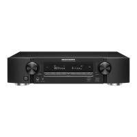
Do you have a question about the Marantz NR1606/U1B and is the answer not in the manual?

Marantz NR1606/U1B Specifications

General IconGeneral
Channels7.2
HDMI Outputs1
4K Ultra HD Pass-throughYes
Dolby AtmosYes
DTS:XYes
Wi-FiYes
BluetoothYes
AirPlayYes
Spotify ConnectYes
Internet RadioYes
Zone OutputZone 2
Input Sensitivity200 mV
Signal-to-Noise Ratio98 dB
Speaker Impedance4-16 ohms
Tuner TypeAM/FM
Ethernet PortYes
DLNA CertifiedYes
Power Output per Channel50W (8 ohms)
Phono InputYes
Frequency Response10 Hz - 100 kHz
Total Harmonic Distortion0.08%
USB PortYes (Front)

Summary

Service Manual

About This Manual

What You Can Do With This Manual

Explains the functionalities of the service manual and how to use its features like search and navigation.

Jump to the Target of a Schematic Diagram Connector

Describes how to navigate to specific connector points within schematic diagrams using reference numbers.

Using Adobe Reader (Windows Version)

Print a Magnified Part of the Manual

Details the steps for printing specific magnified sections of the manual using printer settings.

Magnify Schematic / Printed Circuit Board Diagrams - 2 (Pan & Zoom Function)

Magnify Schematic / Printed Circuit Board Diagrams - 3 (Loupe Tool Function)

Safety Precautions

Cautions During Servicing and Inspection

Important cautions and instructions to be followed during servicing and inspection procedures.

Notes for Schematic Diagram

Notes for Parts List

Handling Semiconductors and Optical Units

Ground for Human Body

Instructions on grounding human body using a grounding band to prevent static discharge.

Technical Specifications

Dimension

Caution in Servicing

Initializing This Unit

Procedure for initializing the unit after replacing microcomputer or peripheral equipment.

Jig for Servicing

Disassembly

Explanatory Photos for Disassembly

1. Front Panel Assy

2. Radiator Assy

3. HDMI PCB

4. SPK PCB

5. TRANS

6. SMPS PCB

Special Mode

Special Mode Setting Button

Explains how to enter special modes using specific button combinations on the unit.

1. Version Display Mode

1.1. Actions

Describes the actions to perform to display the version information of the unit's firmware.

1.4. Error Display

1.5. Version Display in the Setup Menu

2. Panel / Remote Lock Selection Mode

2.1. Actions

Explains how to switch the panel lock and remote lock modes between on and off.

3. Selecting the Mode for Service-related Operations

3.1. Actions

Describes how to select diagnostic modes such as service path check and protection history display.

3.5. Diagnostic Mode (Service Path Check Mode)

3.5.1. Actions

Details the function of confirming problem paths and checking paths after repair.

Diagnostic Path Diagram fig.01

Analog Audio Diagram

3.6. Protection History Display Mode

3.6.1. Actions

Describes how this mode records and displays events when THERMAL, ASO, or DC protection is activated.

3.6.4. Clearing the Protection History

Warning Displays by POWER LED

3.7. Operation Info Mode

3.7.1. Actions

Enables display of accumulated operating time, power on count, and protection counts.

4. Protection Pass Mode

5. CY920 Reboot Mode

6. CY920 Initialization Mode

Jig for Servicing

Procedure After Replacing the Microprocessor, Etc.

Firmware Update Procedure

1. Updating via USB

Explains how to download and update the latest firmware using a USB memory device.

1.3. File Structure on USB Memory

1.5. Start the Update

1.8. The Firmware Update Finishes

1.10. Update Procedure in the Event of a CY920 Error

1.10. About the Error Codes

2. Updating via DPMS

2.1. Network Connection

Lists system requirements and settings for establishing a network connection for firmware updates.

2.3. About the Error Codes

Adjustment

Adjusting Idling Current

Step-by-step procedure for adjusting the idling current of the amplifier unit.

Surround Modes and Parameters

Trouble Shooting

1. Power

Troubleshooting guide for issues related to the unit not powering on.

2. Analog Video

3. HDMI/DVI

3.1. No Picture or Sound is Output (HDMI to HDMI)

Troubleshooting steps for diagnosing issues with no picture or sound output over HDMI.

4. Audio

4.1. Audio Check

A systematic check process to diagnose audio output problems.

4.2. Power AMP (AMP PCB)

5. Network / Bluetooth / USB

5.1. Cannot Connect to the Network

Troubleshooting steps for resolving network connectivity issues.

5.2. Cannot Establish a Bluetooth Connection

5.3. Cannot Recognize the Connected USB Device

5.4. No Picture or Sound is Output

6. SMPS

Clock Flow & Wave Form in Digital Block

Level Diagram Front ch

Block Diagram Analog Audio Diagram

Power Diagram

Wiring Diagram

Printed Circuit Boards

Schematic Diagrams (01/26) SCH01_HDMI SW1

Schematic Diagrams (02/26) SCH02_HDMI SW2

Schematic Diagrams (03/26) SCH03_NET_PHY

Schematic Diagrams (04/26) SCH04_CPU_LEVEL_CHG

Schematic Diagrams (05/26) SCH05_DIGITAL_CNT

Schematic Diagrams (06/26) SCH06_CPU

Schematic Diagrams (07/26) SCH07_FRONT HDMI

Schematic Diagrams (08/26) SCH08_ADV8003

Schematic Diagrams (09/26) SCH09_ADV8003 DDR

Schematic Diagrams (10/26) SCH10_D.SUPPLY

Schematic Diagrams (11/26) SCH11_HDMI TX

Schematic Diagrams (12/26) SCH12_DIR_A.PLD

Schematic Diagrams (13/26) SCH13_DSP

Schematic Diagrams (14/26) SCH14_MAIN DAC

Schematic Diagrams (15/26) SCH15_ADV7850

Schematic Diagrams (16/26) SCH16_SPK

Schematic Diagrams (17/26) SCH17_CNT

Schematic Diagrams (18/26) SCH18_INPUT

Schematic Diagrams (19/26) SCH19_VIDEO

Schematic Diagrams (20/26) SCH20_TUNER

Schematic Diagrams (21/26) SCH21_FRONT

Schematic Diagrams (22/26) SCH22_AMP1

Schematic Diagrams (23/26) SCH23_AMP2

Schematic Diagrams (24/26) SCH24_SMPS

Schematic Diagrams (25/26) SCH25_REG

Schematic Diagrams (26/26) SCH26_FRONT CNT

Exploded View

Packing View

Semiconductors

1. IC's

Details terminal functions and block diagrams for key ICs like R5F564MJCDFC and R5F56108VNFP.

AD8195ACPZ (HDMI : U1022)

PCM9211 (HDMI : U1040)

CS49844A (HDMI : U1073)

W9864G6KH-5 (HDMI : U1023)

PCM1690 (HDMI : U1048)

PCM5100 (HDMI:U1052)

BD34704KS2 (AV : IC4200)

NJM2595MTE1 (AV:IC5401)

2. FL Display

PIN CONNECTION

Details the pinout and connections for the front display unit.
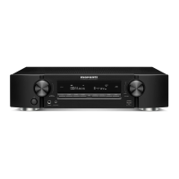
SPK_SCNT PCB Assy

REG_SMPS_FCNT PCB Assy

FRONT PCB Assy

AV PCB Assy

HDMI PCB Assy

7CH_AMP PCB Assy

Exploded View

Packing

Related product manuals