ADJUSTMENT
Adjusting Idling Current
1. Preparation
(1) PrepareaDCvoltmeter.
(2) Placetheunitundernormalusageconditions,awayfromhighlyventilatedareassuchasnexttoanairconditioning
machineorelectricfan.
Thesetrequiresanambienttemperatureof15℃to30℃(59°F~86°F)andstandardhumidity.
(3) SettingsofThisUnit
•POWER(Powersourceswitch) STANDBY
•SPEAKER(Speakerterminal) Noload
(Donotconnectequipmentsuchasspeakersordummyresistors.)
2. Adjustment Procedure
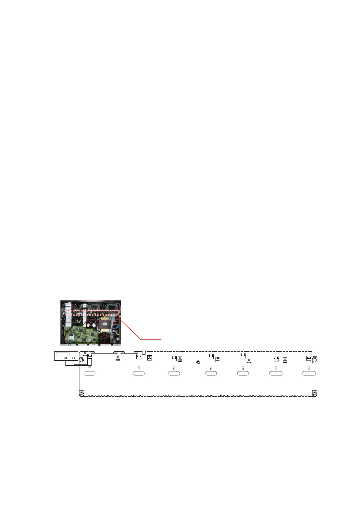
(1) RemovethetopcoverandturnVR4800,VR4801,VR4802,VR4803,VR4804,VR4805,VR4806oftheAMPPCB
counterclockwise(
c
)asfaraspossible.
(2) ConnectDCVoltmetertothetestpoints.
FRONT-Lch :TP4800
FRONT-Rch :TP4802
CENTERch :TP4804
SURROUND-Lch :TP4806
SURROUND-Rch :TP4808
SURROUND-BACKLch :TP4810
SURROUND-BACKRch :TP4813
(3) Connectthepowercordtoanoutlet.Next,pressthepowerbuttontoturnonthepower.
(4) Setthisunitasfollows.
MASTERVOLUME :"---"(
c
min.):turncounterclockwisetothelowestposition.
SPEAKER(Speakerterminal) :Noload
(Donotconnectequipmentsuchasspeakersordummyresistors.)
MODE :MCHSTEREO
FUNCTION :CBL/SAT
(5) TurnVR4800clockwise(
x
)andadjustthevoltageofthetestpointto"2.0mV ± 0.5mVDC."within2minutes.
(6) 10minutesafterthepreliminaryadjustment,turnVR4800andsetthevoltageto"3.0mV ± 0.5mV DC".
(7) Adjustthevariableresistanceofeachchannelusingthesamemethod.(VR48001-VR4806).
F Lch S L ch C ch S R ch F R ch S Back Lch S Back Rch
VR4803
TP4800
TP4806
VR4802
TP4804 VR4804
C
SR
SL
FL
VR4800
TP4808
TP4802
VR4801
VR4805
TP4810
VR4806
TP4813
SBR
SBL
FR
DC Voltmeter
AMP UNIT
65