Explanatory Photos for DISASSEMBLY
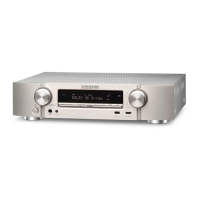
• For the shooting direction of each photos used in this manual, see the photo below.
• A, B, C and D in the photo below indicate the shooting directions of photos.
• The photographs with no shooting direction indicated were taken from the top of the unit.
• Photos of NR1609 U are used in this manual.
The viewpoint of each photograph
(Shooting direction : X) [View from the top]
Attention :
When reinserting the Antenna Cable after it has been disconnected, make sure it is facing the direction
shown in A above.
↓Shooting direction: C↓
↑Shooting direction: D↑
↑Shooting direction: A↑
↓Shooting direction: B↓
�
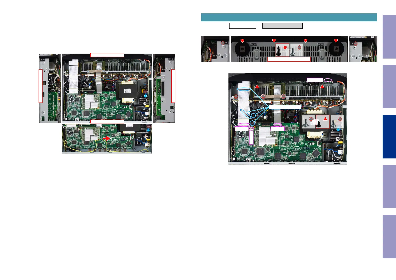
Proceeding : TOP COVER → FRONT PANEL ASSY
(1) Remove the screws.
(2) Remove the screws. Remove the CORD HOLDER and connectors. Remove the FFC.
1. FRONT PANEL ASSY
View from the bottom
x2x4
x2 x2 x1
CP4401
FFC
N1008
FFC
CORD HOLDER
Before Servicing
This Unit
Electrical Mechanical Repair Information Updating
69
 Loading...