SPECIAL MODE
Special mode setting button
b
No. 1 - 4, 6 - 8 : While holding down buttons "
A
", "
B
" and "
C
" simultaneously, press the power button to turn on the power.
b
No. 5, 9, 10 : While the power is on, hold down buttons "
A
" and "
B
" for at least 3 seconds .
No. Mode Button A Button B Button C Descriptions
1
Version Display Mode
(u-COM / DSP Error Display)
DIMMER STATUS -
Displays the version of rmware such as the main rmware or DSP. Errors that have occurred are displayed.
(See 1. Version Display Mode)
2
PANEL / REMOTE LOCK Selection
Mode
M-DAX DIMMER -
Start this unit in the PANEL/REMOTE LOCK selection mode so that PANEL LOCK and Remote Lock can be switched between On and
Off. (See 2. PANEL / REMOTE LOCK Selection Mode)
•PANEL LOCK Mode (with Volume)
Disables reception from all keys and encoders on the front panel except the power button (including the volume).
•PANEL LOCK Mode (without Volume)
Disables reception from all keys and encoders on the front panel except the power button and volume encoder.
•PANEL LOCK mode is turned off
3 Selecting the Mode for Service-related
ZONE2
SOURCE
STATUS -
This is a display for turning on each service-related mode.
Service-related modes : No. 3-1 - No. 3-4 (See 3-1. Selecting the Mode for Service-related)
3-1 Check the Video/Audio path Mode
↑ ↑ -
This is a special mode for service conrmation used during repair work to simplify the conrmation work for the Audio channel /
video channel. (See Service Path Check Mode)
3-2 Protection history display mode
↑ ↑ -
Displays the protection occurrence history. (See 3-2. Protection History Display Mode)
3-3 Operation Info Mode
↑ ↑ -
Displays the accumulated operating time of the unit, the number of times the power was switched on, and the number of occur-
rences of each protection. (See 3-3. Operation Info Mode)
3-4
TUNER STEP Mode
(U and N model only)
↑ ↑ -
Enables reception STEP of the ANALOG TUNER to be changed.
(See 3-4. TUNER STEP mode (U / N only))
4 Protection Pass Mode
DIMMER STATUS
SOUND
MODE
Enables the power to be turned on when protection detection is disabled. (See 4. Protection Pass Mode)
5 Network Initialization Mode
ZONE2
SOURCE
DIMMER -
Network module backup data is initialized. (See 5. Network Initialization Mode)
6 User Initialization Mode
M-DAX
ZONE2
SOURCE
-
Initialize the backup data for the MCU and network module. (Settings for the Installer Setup are not initialized.)
7 Factory Initialization Mode
ZONE2
SOURCE
INTERNET
RADIO
-
Initialize the backup data only for MCU.
(Settings for the Installer Setup are initialized) (Network function settings are not initialized.) (See Initializing this Unit)
8 Clearing the Operation Info
DIMMER
INTERNET
RADIO
-
Clear the accumulated operating time of the unit, the number of times the power was switched on, and the number of occurrences
of each protection. (See 6. Clearing the Operation Info)
9 HDMI Diagnostics Mode
M-DAX DIMMER
This mode is used to identify and solve the cause when there is a connectivity issue with this unit and an HDMI device.
For details on the operating methods and diagnosis procedures, see the HDMI Diagnostics and Troubleshooting guide issued on SDI.
10 Log Capture feature
DIMMER
SOUND
MODE
-
Acquires the Network Module log. The log is deleted when the Network Module is deleted. (See 7. Log Capture feature)
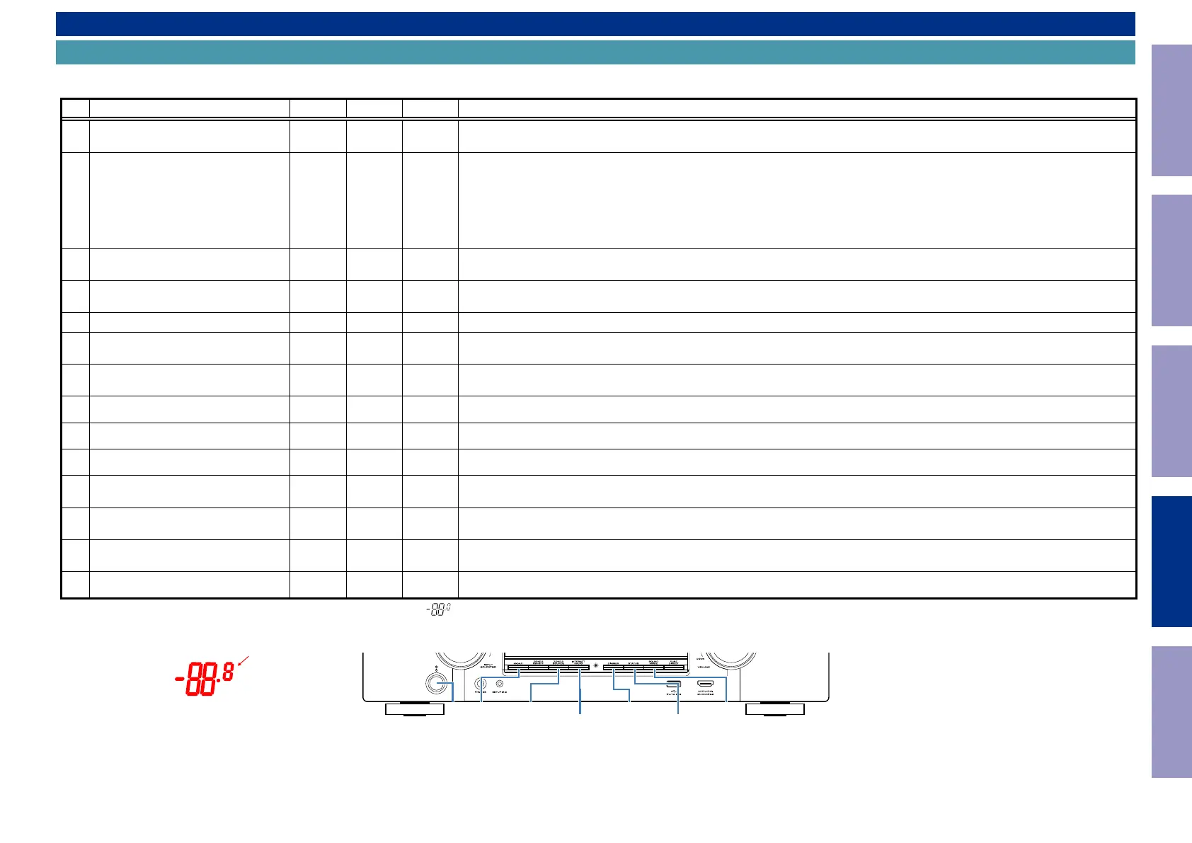
NOTE : If the two indicator lights at the bottom right of the FLD display "
", this means that the unit has entered the special developer’s mode. In this case, the RS-232C communication is not available.
To release this special mode, press and hold the "M-DAX" and "ZONE2 SOURCE" buttons for 3 seconds or more while the power is ON. The RS-232C communication is available when the two indicator lights at the
bottom right of the FLD go out.
All the indicator Lights
INTERNET
RADIO
SOUND
MODE
DIMMER
STATUSM-DAX
X
ZONE2
SOURCE
Before Servicing
This Unit
Electrical Mechanical Repair Information Updating
120