About the photos used for "descriptions of the DISASSEMBLY" section
• The shooting direction of each photograph used herein is indicated on the left side of the respective photograph as
"Shooting direction: ***".
• Refer to the diagram below about the shooting direction of each photograph.
• Photographs with no shooting direction indicated were taken from the top of the set.
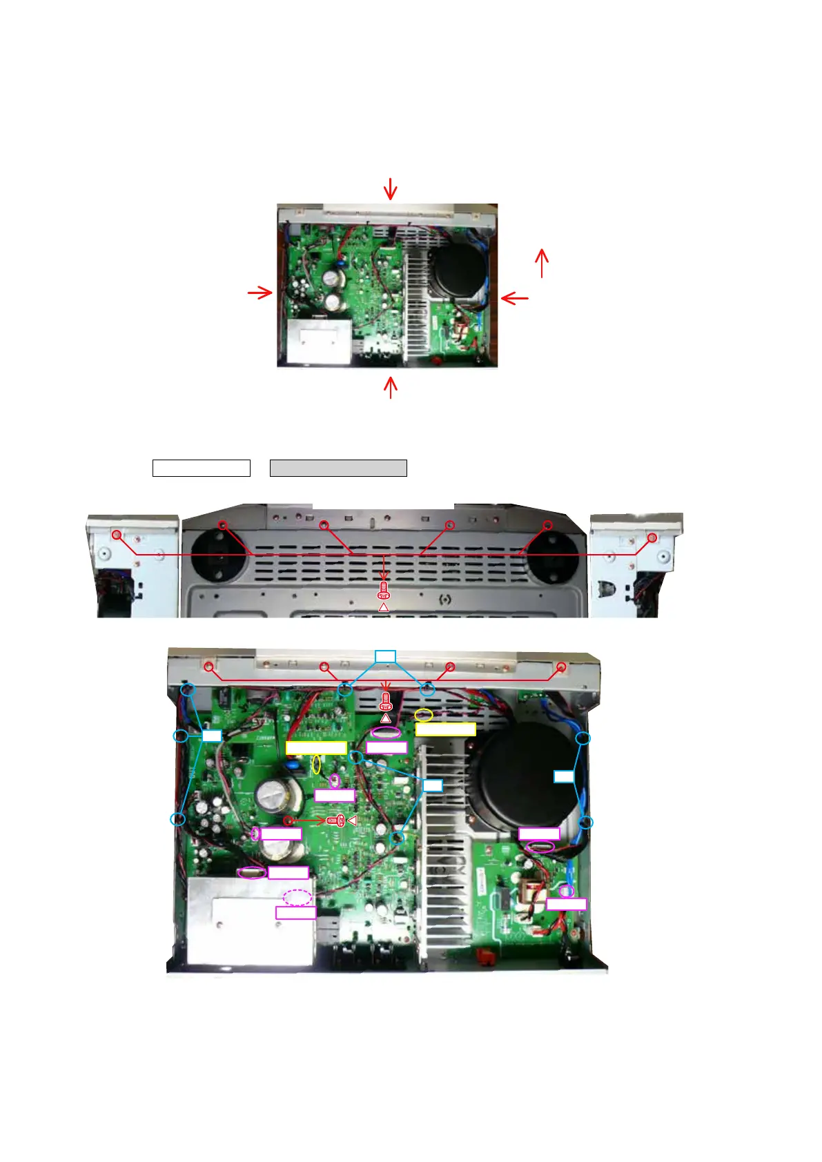
1. FRONT PANEL ASSY
Proceeding : TOP COVER
→
FRONT PANEL ASSY
(1) Remove the screws.
(2) Cut the wire clamp band, then remove the style pin and screws. Disconnect the connector wires.
The viewpoint of each photograph
(Shooting direction X)
[View from the top]
Front side
Shooting direction: B
Shooting direction: D
Shooting direction: C
Shooting direction: A
View from the bottom Shooting direction: CShooting direction: D
N7501
N8504
N8502
N3002
N6001
N3001
BN302
STYLE PIN
STYLE PIN
cut
cut
cut
cut
12
 Loading...