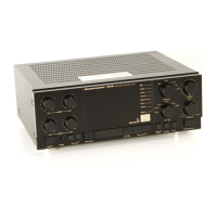
Explanatory Photos for DISASSEMBLY
• For the shooting direction of each photos used in this manual, see the photo below.
• A, B, C and D in the photo below indicate the shooting directions of photos.
• The photographs with no shooting direction indicated were taken from the top of the unit.
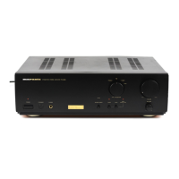
• Photos of PM6006 N1SG are used in this manual.
The viewpoint of each photograph
(Shooting direction : X) [View from the top]
Front side
↑Shooting direction: A↑
↓Shooting direction: B↓
↓Shooting direction: D↓
↑Shooting direction: C↑
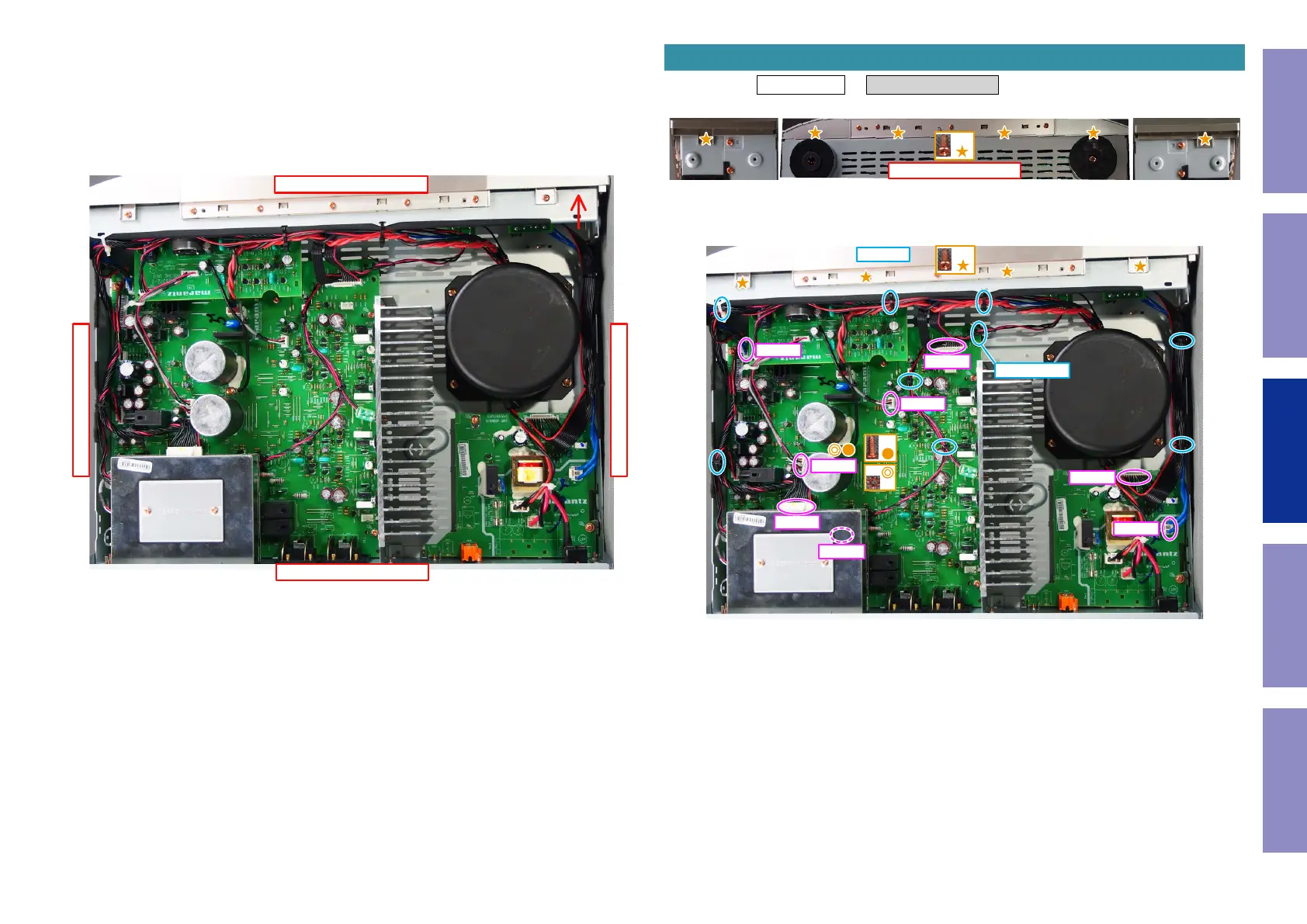
Proceeding : TOP COVER → FRONT PANEL ASSY
(1) Remove the screws.
(2) Remove the screws. Cut the wire clamps, then remove the CORD HOLDERs and connectors.
Remove the STYLE PIN.
1. FRONT PANEL ASSY
View from the bottom
x6
x4
x1
x1
BN302
N3001
N8101
N3002
N6001
N8505
N8504
N7501
CUT x8
STYLE PIN
26
Caution in
servicing
Electrical Mechanical Repair Information Updating