1-7
7. L/R OUTPUT LEVEL ADJUSTMENT
PROCEDURE
Cases adjustment is needs
When a Q201 or Q251 is replaced.
Necessary equipments
• AC voltmeter 2 sets (or Oscilloscope)
• CD TEST DISC: CBC429 Audio signal disc1 (4822-397-
30155)
Connection procedure
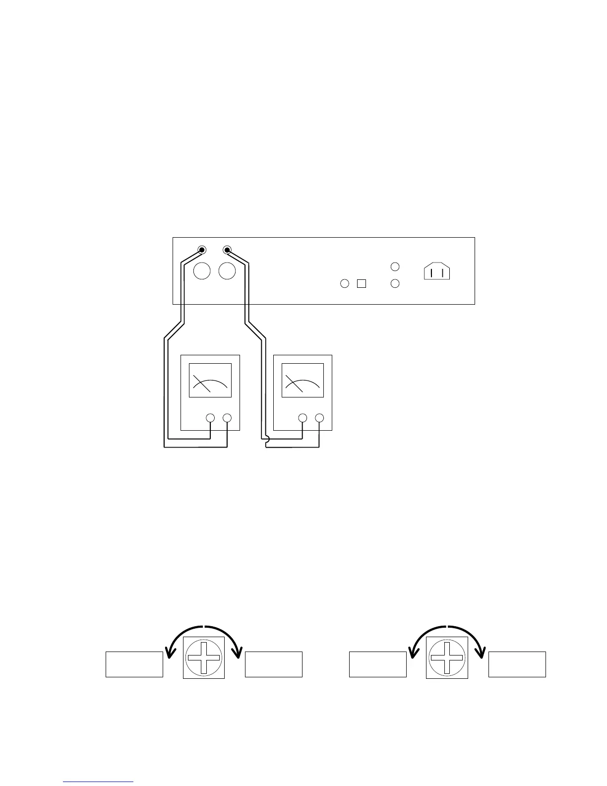
• Connect the ANALOG OUTPUTS terminal (L/R) on the
rear panel and AC voltmeter with cable as follow.
Adjustment procedure
1. Play back the Track 1 (1 kHz 0dB L+R) of the TEST DISC
(SBC429).
2. Adjust trimming resister (R205) according to AC
voltmeter readings of L ch output level and R ch output
level.
3. The output level difference of the L ch and R ch is
adjusted to less than 50mV.
If R205 is turned clockwise, the level of L ch will become
large, and if it turns to anticlockwise rotation, the level of
R ch will become large.
7. L/R出力レベル調整手順
調整が必要な場合
Q201またはQ251を交換した時に調整が必要になります。
必要機器
• 交流電圧計 2台 (またはオシロスコープ)
• CD
テストディスク CBC429 Audio signal disc1 (4822-
397-30155)
接続図
• リアパネルにあるANALOG OUTPUTS端子L、Rをそれぞ
れ交流電圧計に接続します。
調整方法
1. テストディスク(SBC429)のTr.1 (1kHz 0dB L+R)を再生し
ます。
2. 交流電圧計でL ch、R chの出力レベル差50mV未満になる
ように
R205で調整します。
R205を時計方向に回すとL chのレベルが大きくなり、反時
計方向に回すと
R chのレベルが大きくなります。
R205
R ch: Larger
L ch: Smaller
R ch: Smaller
L ch: Larger
RL
––
++
R205
R chレベル大
L chレベル小
R chレベル小
L chレベル大