2-23 2-24
IC602 RH-iX1474GEZZ: SACD Data Processor (IX1474GE) (2/2)
84 DVDD3 - Digital power supply (3.3V) For logic cell
85-88 SD3-SD0 Output MPEG data output
89 SERR Output MEPG data reliability flag (Data error = "L")
90 SBGN Output MEPG output sector synchronous signal (Sector head = "L")
91 SENB Output MEPG data effective flag (Effective = "L")
92 SDCK Output MEPG data transfer clock
93 DVSS - Digital power supply (0V) For logic cell
94 SREQ Input MEPG data request flag (In case of request = "L") Level TTL
95 RSTN Input Hard reset input (In case of reset = "L")
96 DVDD3 - Digital power supply (3.3V) For logic cell
97 STDA Output Status data output
98 STCK Output Status clock output
99 UPWM Output Universal PWM output
100 DVSS - Digital power supply (0V) For logic cell
Pin No.
Terminal
Name
Input/Output Function
Remarks
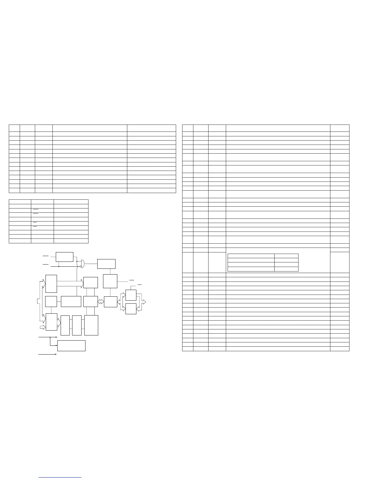
IC603 VHiSC514870SJ: 4Mbit DRAM (SC514870SJ)
Pin No. Terminal Name
Function
10-13, 16-20, 9 A0-A8, A9R Address input
8 RAS Row address strobe
23 CAS Column address strobe
2-5, 24-27 DQ1-DQ8 Data input/Data output
22 OE Output enable
7 WE Write enable
1 VCC Power supply (5V)
15, 28 VSS Ground (0V)
6*, 21* NC Not used
In this unit, the terminal with asterisk mark (*) is (open)
terminal which is not connected to the outside.
Timing
Generator
Timing
Generator
Column
Address
Buffers
Internal
Address
Counter
Row
Address
Buffers
Refresh
Control Clock
Column
Decoders
Sense
Ampliliers
Write
Clock
Generator
I/O
Selector
Output
Buffers
Input
Buffers
Row
De-
coders
Word
Drivers
Memory
Cells
On Chip
Vcc Generator
RAS
CAS
A0 ~ A8
A9R
Vcc Vcc
Vss Vss
WE
OE
DO1 ~ DO8
9
9
1
10
9
8
8
8
8
8
8
8
IC606 RH-iX1473GEZZ: Digital Servo (IX1473GE) (1/3)
1 VSS - Digital ground terminal
2 BCK Output Bit clock (1.4122 MHz) output terminal
3 AOUT Output Audio data output terminal
4 DOUT Output Digital-out output terminal
5* MBOV Output When buffer memory over signal output terminal is over: "H"
6 IPF Output When AOUT output of correction flag output terminal shows the correction impossible
symbol: "H"
7* SBOK Output When CRCC judgment result output terminal of sub-code Q data shows OK: "H"
8* CLCK Input/Output Can be selected by using the clock output/input terminal command bit for reading
sub-code P-W data.
9 VDD - Digital + power terminal
10 VSS - Digital ground terminal
11* DATA Output Sub-code P-W data output terminal
12* SFSY Output Reproductive frame sync signal output terminal
13 SBSY Output When sub-code sync of sub-code block sync output terminal is detected: "H" at the
position of SI
14* SPCK Output Output terminal of the clock (176.4 kHz) for reading processor status signals
15* SPDA Output Processor status signal output terminal
16* COFS Output Correction frame clock (7.35 kHz) output terminal
17* MDNIT Output Can monitor DSP internal flag and PLL clock by using microcomputer commands of
LSI internal signal monitor terminal
18 VDD - Digital + power terminal
19 TESIO0 Input Test input/output terminal. Normally fixed at "L".
20 P2VREF - PLL special 2VREF terminal
21* SPDO Output VCO center frequency shift terminal
22* PDOS Output Phase error (between EFM and PLCK) signal output terminal
(to be used in case of 8-time speed operation)
23 PDO Output Output terminal for phase error signal between EFM signal and PLCK signal
24* TMAXS Output TMAX detection result output terminal. Selected by command bit TMPS.
25 TMAX Output
26 LPFN Input Inversion input terminal of amplifier for low-pass filter
27 LPFO Output Output terminal of amplifier for low-pass filter
28 PVREF - VREF terminal for PLL system
29 VCOREF Input VCO center frequency reference level terminal. Normally fixed at "PVREF".
30 VCOF Output Filter terminal for VCO
31 AVSS - Analog system ground terminal
32 SLCO Output Output terminal of DAC for generating data slice level
33 RFI Input RF signal input terminal
34 AVDD - Analog power terminal
35 RFCT Input RFRP signal center level input terminal
36 REZI Input Input terminal for RFRP zero-cross
37 RFRP Input RF ripple signal input terminal
38 FEI Input Focus error signal input terminal
39 SBAD Input Sub-beam adding signal input terminal
40 TSIN Input Test input terminal. Normally fixed at "Vref".
41 TEI Input Tracking error signal input terminal (Input when tracking servo is ON.)
42 TEZI Input Input terminal for tracking error zero cross
43 FOO Output Focus equalizer output terminal
Pin No.
Terminal
Name
Input/Output Function
Remarks
In this unit, the terminal with asterisk mark (*) is (open) terminal which is not connected to the outside.
TMAX Detection result TMAX Output
Longer than the specified frequency "P2VEFF"
Shorter than the specified frequency "VSS"
Within the specified frequency "HiZ"
 Loading...