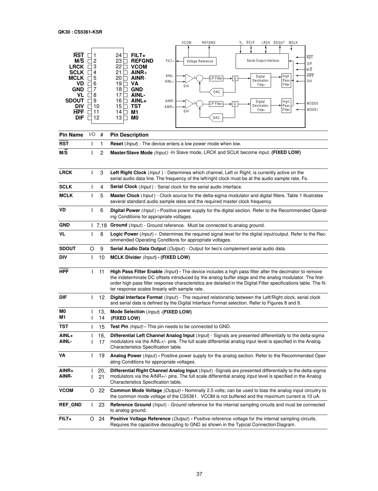
37
I
I
I
I
I
I
I
I
O
I
I
I
I
I
I
I
I
I
I
I
O
I
O
I/O
RST
124
FILT+
M/S
223
REFGND
LRCK
322
VCOM
SCLK
421
AINR
+
MCLK
520
AINR
-
VD
619
VA
GND
718
GND
VL
817
AINL-
SDOUT
916
AINL+
DIV
10 15
TST
HPF
11 14
M1
DIF
12 13
M0
Pin Name
#
Pin Description
RST
1
Reset
(
Input
) - The device enters a low power mode when low.
M/S
2
Master/Slave Mode
(Input)
-In Slave mode, LRCK and SCLK become input. (FIXED LOW)
LRCK
3
Left Right Clock
(
Input
) - Determines which channel, Left or Right, is currently active on the
serial audio data line. The frequency of the left/right clock must be at the audio sample rate, Fs.
SCLK
4
Serial Clock
(
Input
) - Serial clock for the serial audio interface.
MCLK
5
Master Clock
(
Input
) - Clock source for the delta-sigma modulator and digital filters. Table 1 illustrates
several standard audio sample rates and the required master clock frequency.
VD
6
Digital Power
(
Input
)
-
Positive power supply for the digital section. Refer to the Recommended Operat-
ing Conditions for appropriate voltages.
GND
7,18
Ground
(
Input
) - Ground reference. Must be connected to analog ground.
VL
8
Logic Power
(
Input
)
-
Determines the required signal level for the digital input/output. Refer to the Rec-
ommended Operating Conditions for appropriate voltages.
SDOUT
9
Serial Audio Data Output
(
Output
) - Output for two’s complement serial audio data.
DIV
10
MCLK Divider
(Input
) - (FIXED LOW)
HPF
11
High Pass Filter Enable
(Input
) -
The device includes a high pass filter after the decimator to remove
the indeterminate DC offsets introduced by the analog buffer stage and the analog modulator. The first-
order high pass filter response characteristics are detailed in the Digital Filter specifications table. The fil-
ter response scales linearly with sample rate.
DIF
12
Digital Interface Format
(
Input
) - The required relationship between the Left/Right clock, serial clock
and serial data is defined by the Digital Interface Format selection. Refer to Figures 8 and 9.
M0
M1
13,
14
Mode Selection
(
Input
) -(FIXED LOW)
TST
15
Test Pin
(Input)
-
This pin needs to be connected to GND.
AINL+
AINL-
16,
17
Differential Left Channel Analog Input
(
Input
) - Signals are presented differentially to the delta-sigma
modulators via the AINL+/- pins. The full scale differential analog input level is specified in the Analog
Characteristics Specification table.
(FIXED LOW)
VA
19
Analog Power
(
Input
)
-
Positive power supply for the analog section. Refer to the Recommended Oper-
ating Conditions for appropriate voltages.
AINR+
AINR-
20,
21
Differential Right Channel Analog Input
(
Input
) -Signals are presented differentially to the delta-sigma
modulators via the AINR+/- pins. The full scale differential analog input level is specified in the Analog
Characteristics Specification table.
VCOM
22
Common Mode Voltage
(Output)
-
Nominally 2.5 volts; can be used to bias the analog input circuitry to
the common mode voltage of the CS5361. VCOM is not buffered and the maximum current is 10 uA.
REF_GND
23
Reference Ground
(
Input
) - Ground reference for the internal sampling circuits and must be connected
to analog ground.
FILT+
24
Positive Voltage Reference
(
Output
)
-
Positive reference voltage for the internal sampling circuits.
Requires the capacitive decoupling to GND as shown in the Typical Connection Diagram.
Voltage Reference
Serial Output Interface
Digital
Filter
High
Pass
Filter
High
Pass
Filter
Decimation
Digital
Filter
Decimation
DAC
-
+
S/H
DAC
-
+
S/H
AINR+
SCLK
SDOUT MCLK
RST
VCOM LRCK
AINR-
AINL+
AINL-
FILT+
DIF
M/S
HPF
MODE0
MODE1
REFGND
V
L
DIV
Q
LP Filter
QLP Filter
QK30 : CS5361-KSR