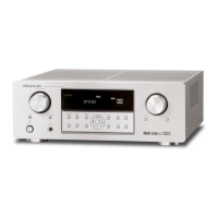
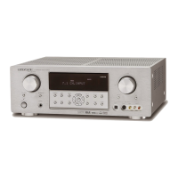
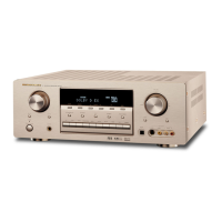
AV Surround Receiver
SR4500
/
PS4500
Part no. 90M07BW855010
First Issue 2004.06
ecm
Service
Manual
SR4500 /A1B/N1B/U1B
K1G/L1G/N1G
A1S/N1S/U1S
Please use this service manual with referring to the user guide (D.F.U) without fail.
SR4500
TABLE OF CONTENTS
SECTION PAGE
1. TECHNICAL SPECIFICATIONS ............................................................................................ 1
2. TECHNICAL DESCRIPTION ................................................................................................. 4
3. WIRING DIAGRAM ................................................................................................................7
4. BLOCK DIAGRAM .................................................................................................................9
5. SCHEMATIC DIAGRAM ........................................................................................................11
6. PARTS LOCATION .............................................................................................................. 27
7. IC DATA ................................................................................................................................ 38
8. EXPLODED VIEW AND PARTS LIST .................................................................................. 45
9. POWER AMPLIFIER ADJUSTMENT ................................................................................... 52
10. SERVICE MODE .................................................................................................................. 53
11. SYSTEM ERROR ................................................................................................................ 55
12. UPDATE FIRMWARE .......................................................................................................... 56
13. ELECTRICAL PARTS LIST .................................................................................................. 58
SURROUND
AV SURROUND RECEIVER SR4500
DOWN
UP
VOLUME
INPUT SELECTOR
POWER ON/OFF PHONES
STANDBY
MUTE
7.1CH INPUT
S. SPEAKER B
ATT
PURE
SETUP
DIRECT
SIMPLE
AUTO
HT-EQ
MENU
ENTER
DISPLAY
MEMORY
CLEAR
T-MODE
EXIT
BAND
MODE
DISP MULTI AUTO TUNED ST V
–
OFF NIGHT PEAK ANALOG
DIGITAL
ATT
SLEEP
SURR
AUTO
DIRECT DISC 6.1 MTX 6.1 EQ
DIGITAL
SURROUND
PCM
L
C
R
SL S SR
LFE
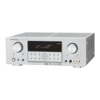
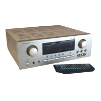
PS4500 /F1N
AV Surround Amplifier
PS4500