4
If another component in your system inverts the signal, you may
connect the Nº27.5 for inverting operation to achieve a non-inverting
state for the entire system. In this mode, the output signal of the
amplifier is 180° out of phase with the input signal.
For inverting operation, you will connect your preamplifier's main
output cables to the XLR-type inputs on the rear panel of the Nº27.5.
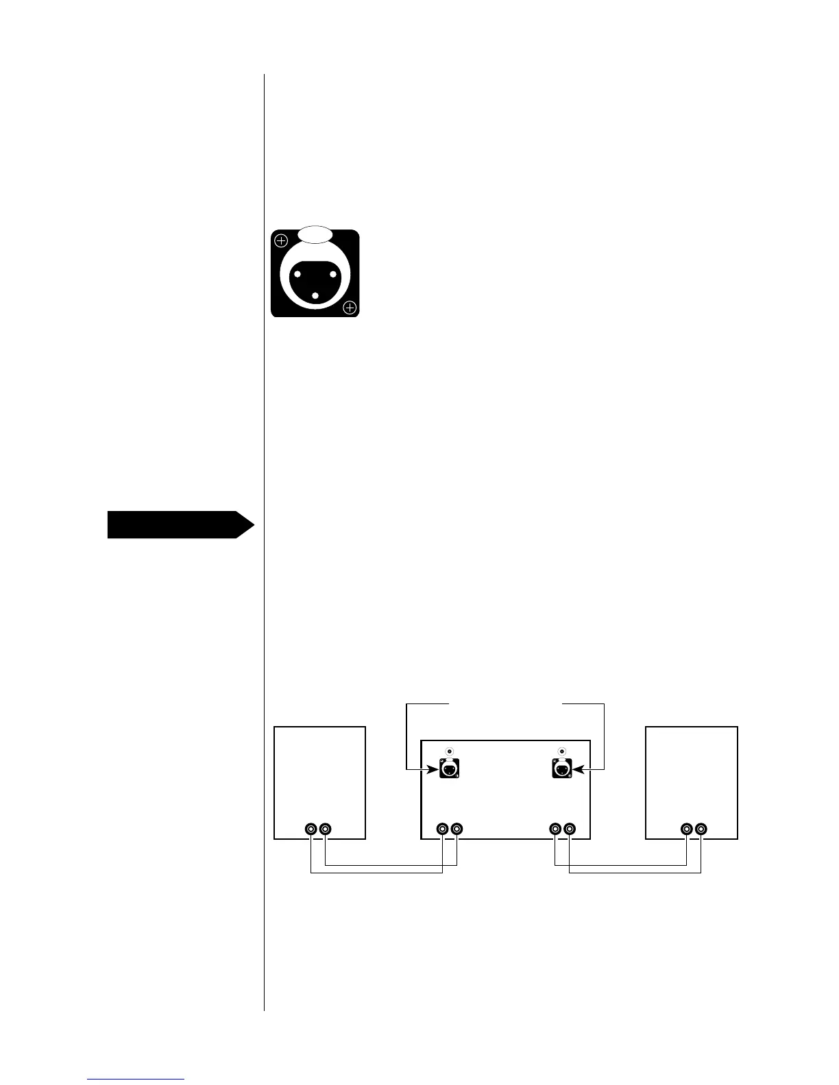
The pin assignments of these connectors are
Pin 1: Signal ground
Pin 2: Signal + (Non-inverting)
Pin 3: Signal – (Inverting)
Connector ground lug: Chassis ground
Connect the XLR-type male line-mount connectors to your
preamplifier's main output cables so that signal + connects to Pin 3
and signal ground connects to Pin 1. At the amplifier end of the
cables, connect Pin 2 to Pin 1 inside the XLR-type male line-mount
connectors with a piece of copper buss wire (or similar material).
Note: If you prefer not to connect Pin 2 to Pin 1 inside the XLR-type
male line-mount connectors, pre-shorted RCA-type input
connectors are available from your Mark Levinson dealer. Insert
one of these pre-shorted connectors into each of the RCA-type
inputs on the rear panel of the Nº27.5 (for single-ended inverting
operation only — NEVER use a pre-shorted connector when
connecting the Nº27.5 for balanced operation).
Before inserting the output-cable connectors, remove the shorting
strap from the Nº27.5's XLR-type inputs. Connect your preamplifier's
left-channel main output to the left-channel XLR-type input on the rear
panel of the Nº27.5. Connect your preamplifier's right-channel main
output to the right-channel XLR-type input on the rear panel of the
Nº27.5.
Single-ended inverting
operation
Figure 3: Female input
connector
PUSH
21
3
PUSHPUSH
+–
Nº27.5
–+
–+
Left
Loudspeaker
+–
Right
Loudspeaker
From preamplifier main output
Right
channel
Left
channel
Figure 4: Connections for
single-ended inverting
operation
PRECAUTION