9. Align the phono module mounting bracket mounting screw (F) with the mounting terminal
(B) on the main circuit board. Then, use the supplied flat-blade screwdriver to secure the
phono module to the main circuit board. Take care not to “over-tighten” the mounting screw.
8
Installation Instructions & Release Notes Mark Levinson
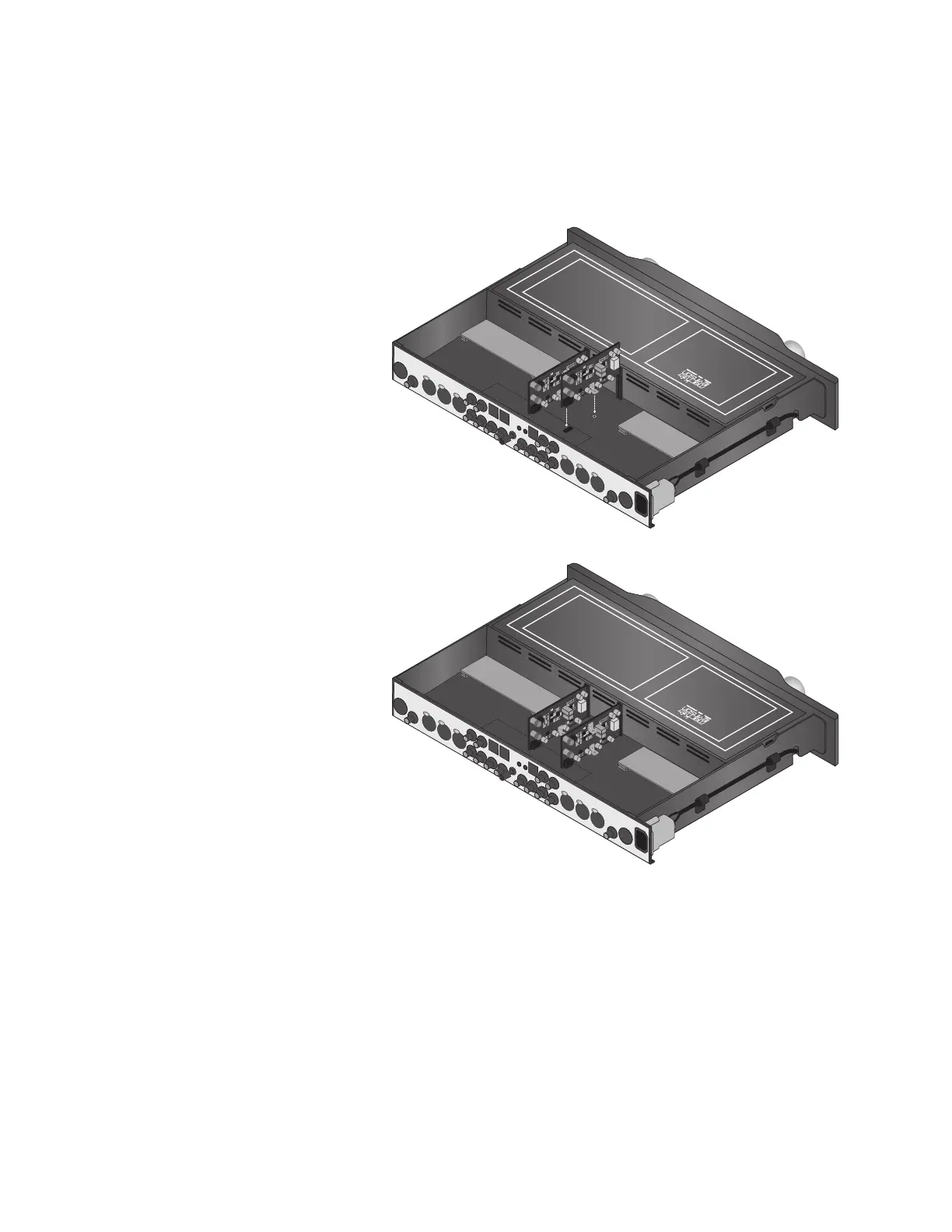
10. Gently slide the second
phono module into the
right-most insertion slot
(A) as shown in the
illustration to the right.
The socket at location P10
(E) on the phono module
will connect with the
plug at location P300 (C)
on the main circuit board,
and the phono module
mounting bracket (F) will
align with the mounting
terminal (B) on the main
circuit board.
11. Align the phono module
mounting bracket mount-
ing screw (F) with the
mounting terminal (B) on
the main circuit board.
Then, use the
supplied flat-blade
screwdriver to secure
the phono module to the
main circuit board. Take
care not to “over-tighten”
the mounting screw.
12. Replace the top cover from the Nº326S, gently sliding it toward the front panel.
13. Place the Nº326S upside-down on the work surface. Take care to avoid “dropping” the Nº326S
on the work surface once the top cover is replaced.
14. Use the provided 1/8-inch hex-key to replace the four screws that secure the feet and the top
cover. These screws are identified in the illustrations at the bottom of page 6.