Phono Input Settings
When the phono modules are not installed, the stereo input con-
nector labeled 7 serves as the phono input connector. This input
is renamed PHONO within the setup menu, and new parameters
and settings are added to its Set Inputs menu. Other inputs and
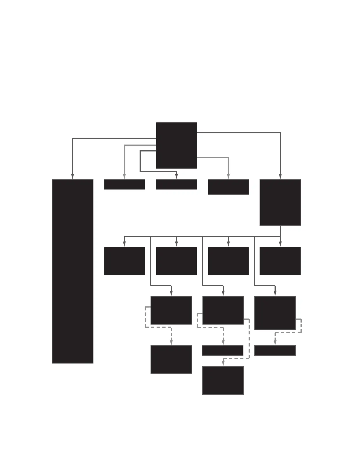
setup menus are not affected. The revised setup menu is shown
below.
10
Installation Instructions & Release Notes Mark Levinson
Name= PHONO
Gain= +12 dB
Offset= 0.0
Bal= <-0.0->
Rec.Out=NONE
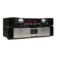
The front panel display provides one-line viewing of the setup menus shown here, indicating the current menu item.
VOLUME UP
VOLUME DOWN
SELECT NEXT
SELECT PREV
INTENSITY
MUTE KEY
MONO KEY
POLARITY KEY
STANDBY KEY
ENTER KEY
SETUP KEY
BALANCE KEY
EXIT STANDBY
GO STANDBY
GO INPUT 1
GO INPUT 2
GO INPUT 3
GO INPUT 4
GO INPUT 5
GO INPUT 6
GO INPUT 7
GO MUTE
GO UNMUTE
GO BALANCE
EXIT BALANCE
DISPLAY OFF
DISPLAY DIM
DISPLAY HALF
DISPLAY FULL
12v,L
5v,P
-80.0 to -10.0 40.0 to 80.0
Name=INPUT 1
Gain= +6 dB
Offset= 0.0
Rec.Out=NONE
Name=INPUT 3
Gain= +6 dB
Offset= 0.0
Rec.Out=NONE
Name=INPUT 2
Gain= +6 dB
Offset= 0.0
Rec.Out=NONE
Name=INPUT 4
Gain= +12 dB
Offset= 0.0
Rec.Out=NONE
+0 dB
+6 dB
+12dB
+18dB
NONE
#1
#2
BOTH
-20.0 to +20.0
<-6.0 to 6.0->
No326S Setup
Set Inputs
Teach IR
Mute = -20.0
MaxVol= 80.0
Trig.= 12v,L
Sw 1.00 B.18
Set Input 1
Set Input 2
Set Input 3
Set Input 4
Set Input 5
Set Input 6
Set Phono 7
Name=INPUT 6
Gain= +12 dB
Offset= 0.0
Rec.Out=NONE
Name=INPUT 5
Gain= +12 dB
Offset= 0.0
Rec.Out=NONE