MGT 240M–1200M 3” NXT2 - SYSTEM 14 DEMAND
OPERATION
31
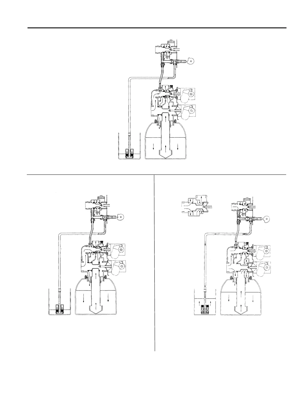
4 SLOW RINSE POSITION
5 RAPID RINSE POSITION
6 BRINE TANK REFILL POSITION
Hard water enters at valve inlet ows thru injector nozzle and throat down thru the mineral into the
bottom distributor up the distributor tube around the piston and out the drain..
Hard water enters at valve inlet ows thru the regeneration
valve directly down thru the mineral into the bottom distributor
up the distributor tube around the piston and out the drain.
Hard water enters at valve inlet ows thru nozzle and thru throat to
brine valve to rell the brine tank. Inlet ow also continues down thru
mineral to the bottom distributor. Conditioned water ows up thru the
distributor tube, around the piston and out the outlet. Note: An option
is available to keep service valve in by-pass position until the end of
brine tank rell cycle.
DRAIN
INLET
DRAIN
INLET
SERVICE
OUTLET
INLET
DRAIN
INLET
 Loading...