[7] ENGINE/SHAFT HOUSING
ASSEMBLY
1. Assemble the engine onto the shaft housing. Make sure
the shaft is fully and correctly up to the shank, then
tighten the four screws A. (Fig. 7-1)
2. In the case of a backpack type reaper, insert the flexible
shaft ass’y metal fitting (E1) while pulling up the knob
(D) of the flexible holder (C), then release your hand
from the knob (D). Match the position of the flexible
inner shaft end (F1) with the mating square hole, and
push in the end from the E2 side. (Fig.7-2)
Then, insert the flexible inner shaft ass’y metal fitting
(E2) while pushing the knob (G).
At that time, be careful so that the flexible inner shaft
end (F2) enters the mating square hole. After the end
(F2) enters the mating hole, release your hand from the
knob (G). (Fig.7-3)
[8] HANDLE GRIP/HANDLE/THROTTLE
WIRE ASSEMBLY
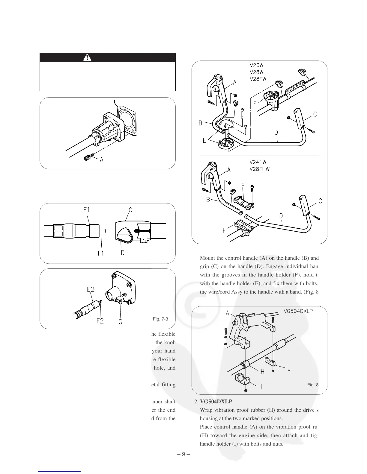
Mounting of handle grip
1. Double handle
Mount the control handle (A) on the handle (B) and the
grip (C) on the handle (D). Engage individual handles
with the grooves in the handle holder (F), hold them
with the handle holder (E), and fix them with bolts. Fix
the wire/cord Assy to the handle with a band. (Fig. 8-1)
2. VG504DXLP
Wrap vibration proof rubber (H) around the drive shaft
housing at the two marked positions.
Place control handle (A) on the vibration proof rubber
(H) toward the engine side, then attach and tighten
handle holder (I) with bolts and nuts.
Do not run the engine without shaft housing
attached, as the clutch could fly off.
DANGER
– 9 –
Fig. 7-1
Fig. 7-2
Fig. 7-3
Fig. 8-1
Fig. 8-2