– 10 –
Attach and tighten handle holder (J) with bolts and nuts.
(Fig.8-3)
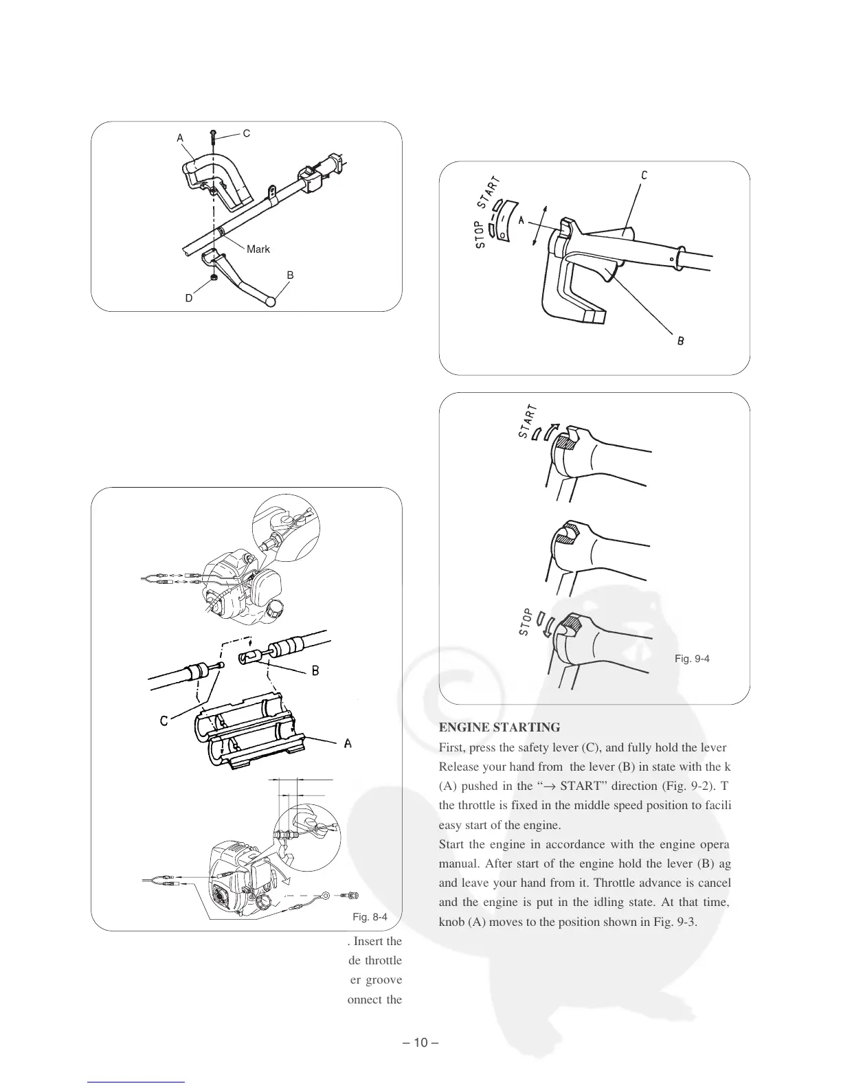
3. Loop handle
The loop handle consists of loop handle body (A),
handle holder (B), Setting bolts M5 × 30 (C) and nuts
M5 (D).
Set the loop handle body at the marked position on the
drive shaft housing, then attach and tighten handle
holder (B) with bolts (C) and nuts (D).
Connection of throttle wire
Open the engine side throttle wire joint cover (A). Insert the
control handle side wire end (C) in the engine side throttle
wire end (B). Match the end with the joint cover groove
positionally as it is, and close the joint cover. Connect the
control handle/engine cord Assy. (Fig. 8-4)
[9] STARTING AND STOPPING THE
ENGINE
MODEL: V24IW V26W V28W V28FW V28FHW
VG504DXLP
ENGINE STARTING
First, press the safety lever (C), and fully hold the lever (B).
Release your hand from the lever (B) in state with the knob
(A) pushed in the “→ START” direction (Fig. 9-2). Then,
the throttle is fixed in the middle speed position to facilitate
easy start of the engine.
Start the engine in accordance with the engine operation
manual. After start of the engine hold the lever (B) again,
and leave your hand from it. Throttle advance is cancelled,
and the engine is put in the idling state. At that time, the
knob (A) moves to the position shown in Fig. 9-3.