Installation
MZ034
English
3
133
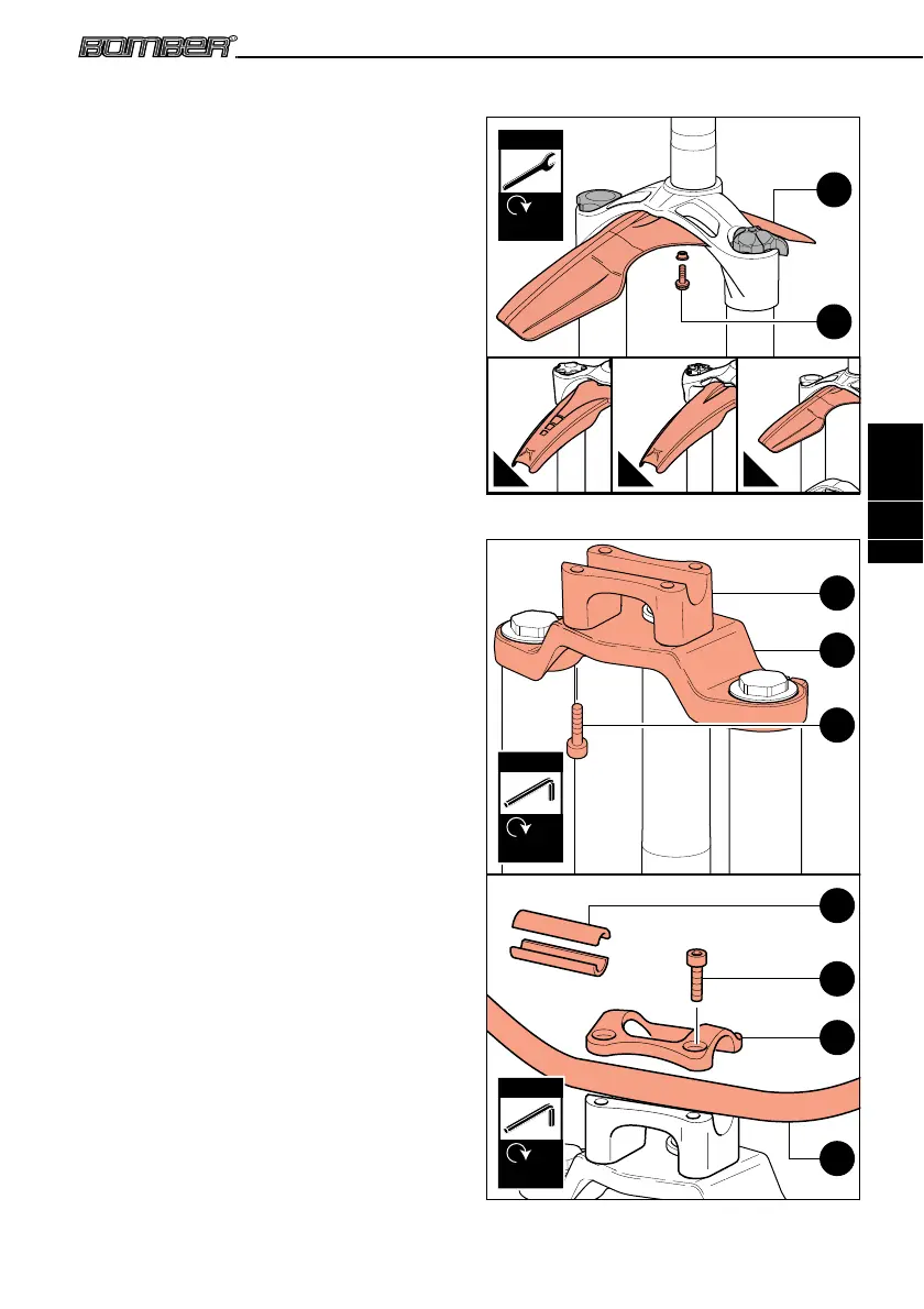
3.5 Fender Installation
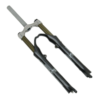
A fender may be installed on the following
models: 66, 888, All Mountain, Junior T, and Z1.
The fender may be provided with the fork, or
purchased separately.
To install the fender, first insert the support
bushing between the screw and fender (see 8A
of Picture 8). Tighten the screw to the required
torque (6±1 Nm) using a 8mm spanner (see 8B
of Picture 8).
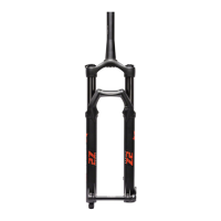
Three different models of fender can be
supplied. The first can be installed on forks of
the 66 and 888 series (see A of Picture 8), the
second on the All Mountain series (see B of
Picture 8), and the third on the Junior T and Z1
series (see C of Picture 8).
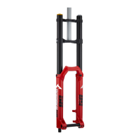
3.6 Handlebar Clamp Installation
Dual-crown model forks use a handlebar clamp.
The handlebar clamp may be sold together with
the fork, or purchased separately.
3.6.1 Handlebar Clamp Installing On All
Dual Crown Models (except the
888 Series)
To install the handlebar clamp, please carefully
follow the instructions below:
• Place the lower mounting segment of the
handlebar clamp on the upper crown of the
fork (see 9A & 9B of Picture 9).
• Align the corresponding holes from each of
these components.
• Secure the lower mounting segment of the
handlebar clamp to the upper crown of the
fork by tightening the screws to the required
torque (10±1 Nm) using a 5mm Allen key (see
9C of Picture 9).
• Place the handlebar into the lower mounting
segment of the handlebar clamp, being sure
that it is centered (see 9D of Picture 9).
• Place the upper segment of the handlebar
clamp over the handlebar (see 9E of Picture
9).
• Align the holes of the upper segment with the
corresponding holes of the lower mounting
segment.
• Secure the handlebar in place by tightening
each screw to the required torque (10±1 Nm)
using a 5mm Allen key (see 9F of Picture 9).
For installation of handlebars having different
diameters, “reduction sleeves” may be placed around
the handlebar (between the handlebar and each
segment of the handlebar clamp) to ensure the
handlebar is held in place (see
9G
of
Picture 9
).
Picture 8 - Fender Installation
Picture 9 - Handlebar Clamp Installation
6±1 Nm
8 mm
8A
8B
A B C
5 mm
10±1 Nm
5 mm
10±1 Nm
9A
9G
9D
9C
9B
9F
9E