PD 10 S - PD 10.6 S
- 14
GB
GB
PD 10.6 S
2 6 35
11 10 9
C
I
D
B
F E
L
H
1 7
4 8
G
G
L
PD 10 S
11
8 9
3
13
5
21
14
12
4
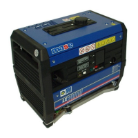
2 GENERAL CHARACTERISTICS
The generators have been designed for use in the industrial
field, using highly reliable 3000 rpm air-cooled diesel
engines. Particular attention has been paid to the degree
of protection against external agents, engine protection
and protection of the electrical parts against overload or
overheating, adopting automatic systems able to stop the
generator in the event of malfunctioning.
The generators are particularly quiet thanks to an internally
insulated soundproof casing and an advanced soundproof
system for combustion smoke exhaust.
The alternators used are the synchronous self-energized
type with electronic voltage adjustment.
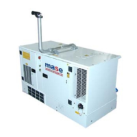
2.1 CONFIGURATIONS
One of the characteristics is that it can be supplied in
different configurations:
1) For use as fixed installation;
2) With slow trailer with fixed drawbar.
It is possible to change from a configuration for fixed
installation to mobile and vice versa.
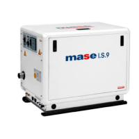
2.2 COMPOSITION OF GENERATOR UNIT
The generator unit is essentially composed of the following
components.
A - Fixed frame
B - Openable cowling engine side
C - Openable cowling alternator side
D - Instrument and sockets panel
E - Fuel tank cap
F - Lifting hook
G - Handle
H - Support
I - Wheel
L - Air inlet
2.3 INSTRUMENT PANEL
Each generator is fitted with an instrument panel for
commands and controls with the following components.
1 - Ignition key
2 - Hour counter
3 - Voltmeter
4 - Ground connector
5 - Emergency stop button
6 - Magnetothermal differential switch 3P+N+T,16A
(GENERAL SWITCH 1-2)
7 - Magnetothermal differential switch 2P+T,25A
(GENERAL SWITCH 3)
8 - Single-phase socket, EC 230V 32A, 2P+GND
9 - Single-phase socket, EC 230V 16A, 2P+GND
10 - Three-phase socket, EC 400V 16A, 3P+N+GND
11 - Remote control connector
12 - 230V - 400V Selector
13 - General magnetothermal switch 2P+T,32A
14 - Magnetothermal switch 16A