Model: MTS200 (1U)
Doc. Ref. no. : m08/om/201
Issue no. : 03
User’s Manual Page 22 of 195 Page 22 of 195
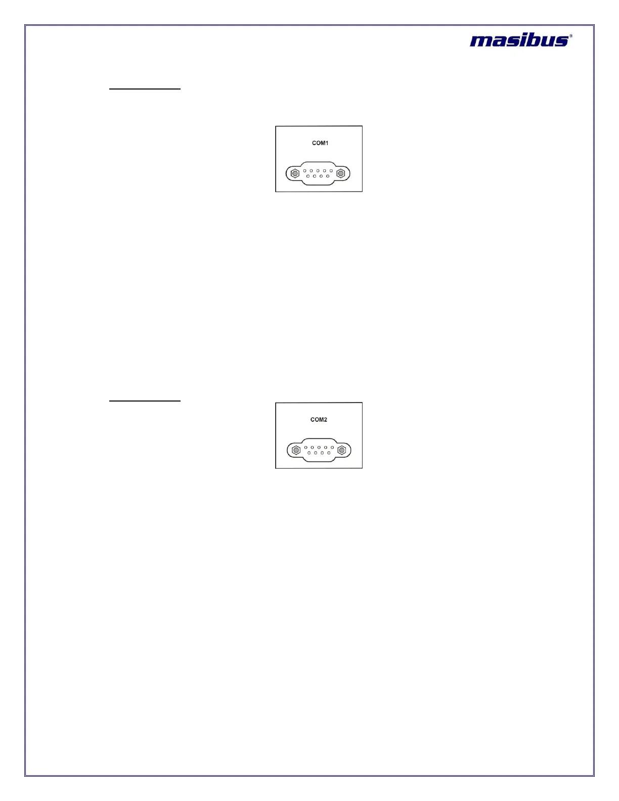
7. COM1 terminal:
COM1 terminal on back plane is RS-232/RS-485 electrical standard DB-9 female connector as
shown in figure 5.9.
Figure 5-9 COM1 terminal
masTER T-Sync Model MTS200 provides serial time frame NMEA format on its COM1 terminal.
This terminal provides NMEA time output either in RS-232 electrical standard or RS-485 electrical
standard as per specified during unit order. If nothing specified, the factory set settings of COM1
terminal is as per RS-232 electrical standard output.
If Configuration of COM1 terminal is as per RS-232 standard, cross cable (having connection on
Pin2, 3 and Pin5) can be used to provide NMEA serial time frame to other peripherals. Pin 4 of
COM1 connector is used to provide 1PPS signal in RS-232 format.
If Configuration of COM1 terminal is as per RS-485 standard, Pin 7 of DB-9 connector will act as
D+ line and Pin 8 will be D- line.
masTER T-Sync Model MTS200 model is available with 1 NMEA serial output as standard option.
8. COM2 terminal:
Figure 5-10 COM2 terminal
COM2 terminal on back plane is RS-232/RS-485 electrical standard DB-9 female connector as
shown in figure 5.10. masTER T-Sync Model MTS200 provides serial time frame T-format / NGTS
format on its COM2 terminal and can also be used for masTER T-Sync Model MTS200
configuration. This terminal connection will be as per RS-232 electrical standard or RS-485
electrical standard as per specified during unit order. If nothing specified, the factory set settings
of COM2 terminal is as per RS-232 electrical standard output.
If Configuration of COM2 terminal is as per RS-232 standard, cross cable (having connection on
Pin2, 3 and Pin5) can be used for configuration and to provide serial time frame to other
peripherals. Pin 4 of COM2 connector is used to provide 1PPM signal in RS-232 format.
If Configuration of COM1 terminal is as per RS-485 standard, Pin 7 of DB-9 connector will act as
D+ line and Pin 8 will be D- line.