Model: MTS200 (1U)
Doc. Ref. no. : - m08/om/201
Issue no.: 03
Page 33 of 195 User’s Manual
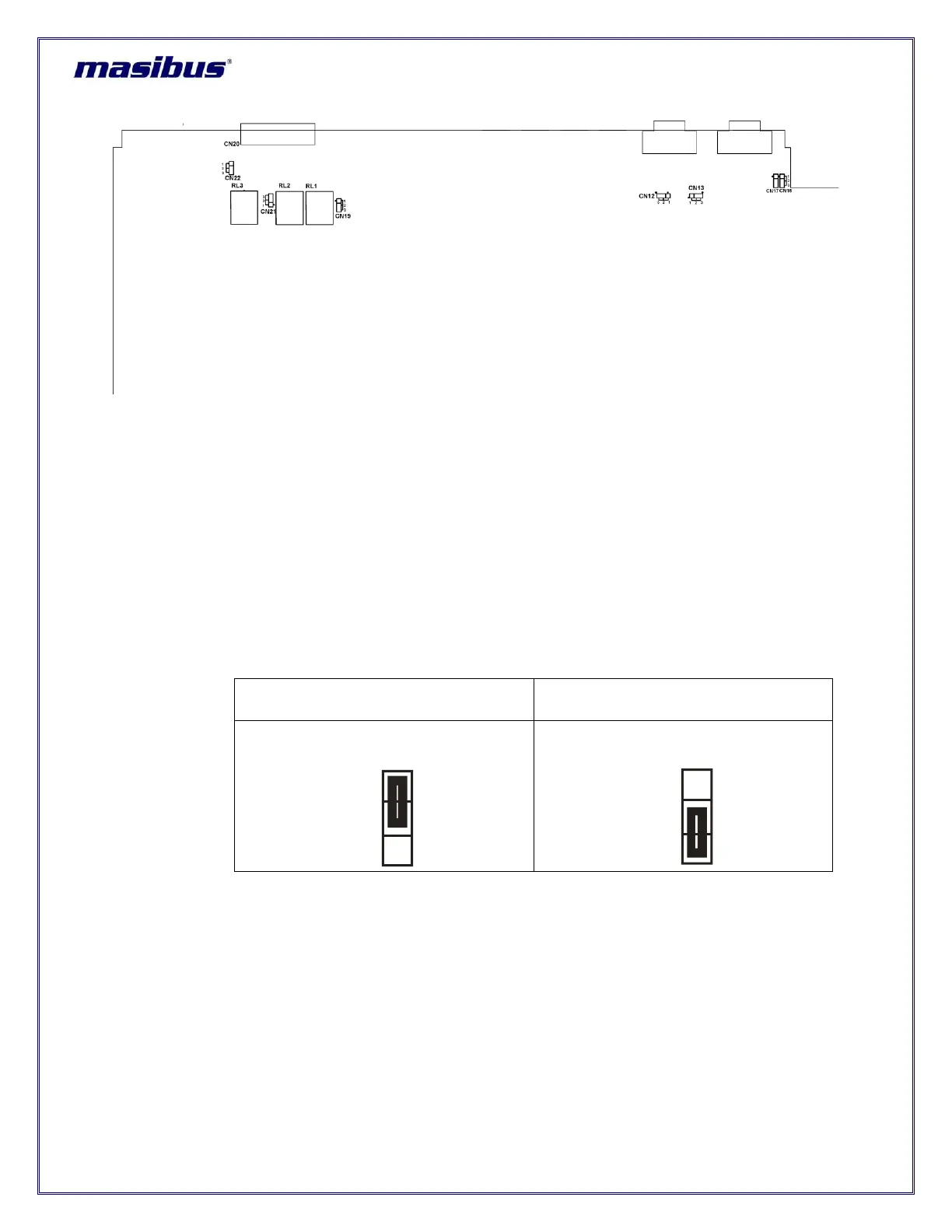
Figure 7-1
mas
TER T-Sync Model MTS200 Main board (Top View)
7.1 Relay Contact Output Configurations:
The factory default settings of Relay contacts for Power, Watchdog and GPS LOST alarm, available on
rear panel of unit are as per C-NO contacts (if any special request is not provided for setting relay output
contacts configuration). If required, operator can change the relay contact from C-NO to C-NC contact as
explained in below details.
7.1.1 POWER relay contacts:
CN20 3-pin jumper on main card is used to change the relay contact for POWER relay contacts. Operator
has to remove black jumper from its current position to required position as explained in below images.
Refer below figure for C-NO jumper position configuration and C-NC jumper position configuration.
Table 7-1 Power Relay Configuration
7.1.2 GPS LOST relay contacts:
CN22 3-pin jumper on main card is used to change the relay contact for GPS LOST relay contacts.
Operator has to remove black jumper from its current position to required position as explained in below
images.
Refer below figure for C-NO jumper position configuration and C-NC jumper position configuration.