Masport Inbuilt Gas Fireplace - 8 -
FLUE SYSTEM
THE APPLIANCE MUST NOT BE CONNECTED TO A
CHIMNEY SERVING A SEPARATE SOLID FUEL
BURNING APPLIANCE.
This appliance is designed to attach to a 100mm
diameter type B-Vent or approved flexi-liner or listed
gas fuel type flue liner running the full length of the
chimney. A minimum flue height of 3.6m is
recommended and it maybe necessary to extend
beyond this. B-Vent flue must be supported by a flue
support - supplied by flue manufacturer. The Masport
Insert incorporates its own internal draft hood, so no
additional external draft hood is required.
Periodically check that the flue is unrestricted and an
adequate draft is present when the unit is in operation.
Install to AG 601, NZS 5261 or local codes.
Fire Installation
1) Remove the top and bottom louvres or grilles.
These lift up and then out. The bottom one has a
centre retaining screw, which must be turned 90°
anticlockwise first. (When refitting, simply press
the screw in to secure the louvre or grille).
2) Slide the fireplace into the recess and adjust the
case position so that it is level and its front top
flange is in line with the face of the fireplace
surround. Where seismic restraint is necessary,
screw the bottom of the case to the base of the
fireplace recess. The base of the fireplace must be
levelled by for example grouting to prevent
vibration from possible fan imbalance.
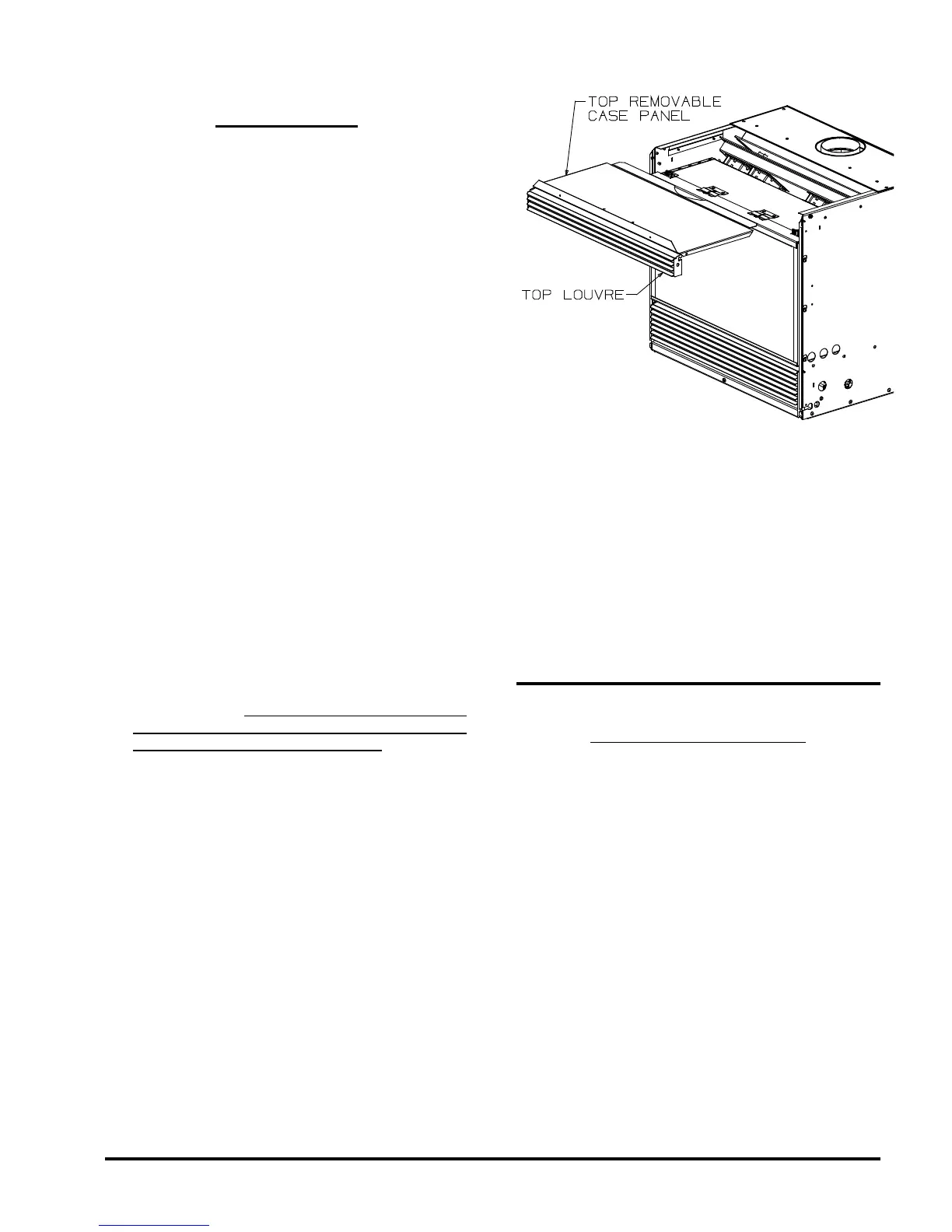
3) If space above the case for positioning and fixing
the flue is limited, greater access can be provided
by first removing the top louvre or grille by lifting it
upwards and outwards.
4) Then remove the 2 screws holding the top sliding
panel, one is located at each side of the fire. The
top front section of the case can now slide out as
illustrated to increase access.
5) Attach the flue to the flue spigot. The flue spigot of
the appliance will fit inside a standard flue and may
be fastened directly to the flue by sheet metal
screw or a B-Vent, single wall flue connector (not
available from Masport).
6) Once the flue is connected, reassemble the fire.
Note: Final gas connection should be after unit is
in place to avoid damage to line when
pushing the unit into position.
Combustion and Ventilation Air
WARNING: This appliance needs fresh air for safe
operation and must be installed with provisions for
adequate combustion and ventilation air available
to the room in which it is to be operating.
Air for combustion is drawn in through the front of the
unit; therefore, this area must be kept clear of any
obstructions.
GAS CONNECTION
GAS CONNECTION WARNING:
Installation must be carried out by a registered installer
who, on completion of the installation, must issue a
certificate of compliance, in accordance with national
and/or local codes. If a certificate of compliance is not
issued then the Masport warranty may be void..
The gas connections are a 3/8” flare for New Zealand
& 1/2" flare for Australia.
When connecting the gas, ensure that the control
valve or pressure regulator is not twisted during this
procedure (such damage is not covered by Masport
warranty).
 Loading...