Masport Inbuilt Gas Fireplace - 9 -
FASCIA INSTALLATION
Sofia & Madrid EIS Models
1) Lay the fascia panels face down on something soft
to prevent them from being marked.
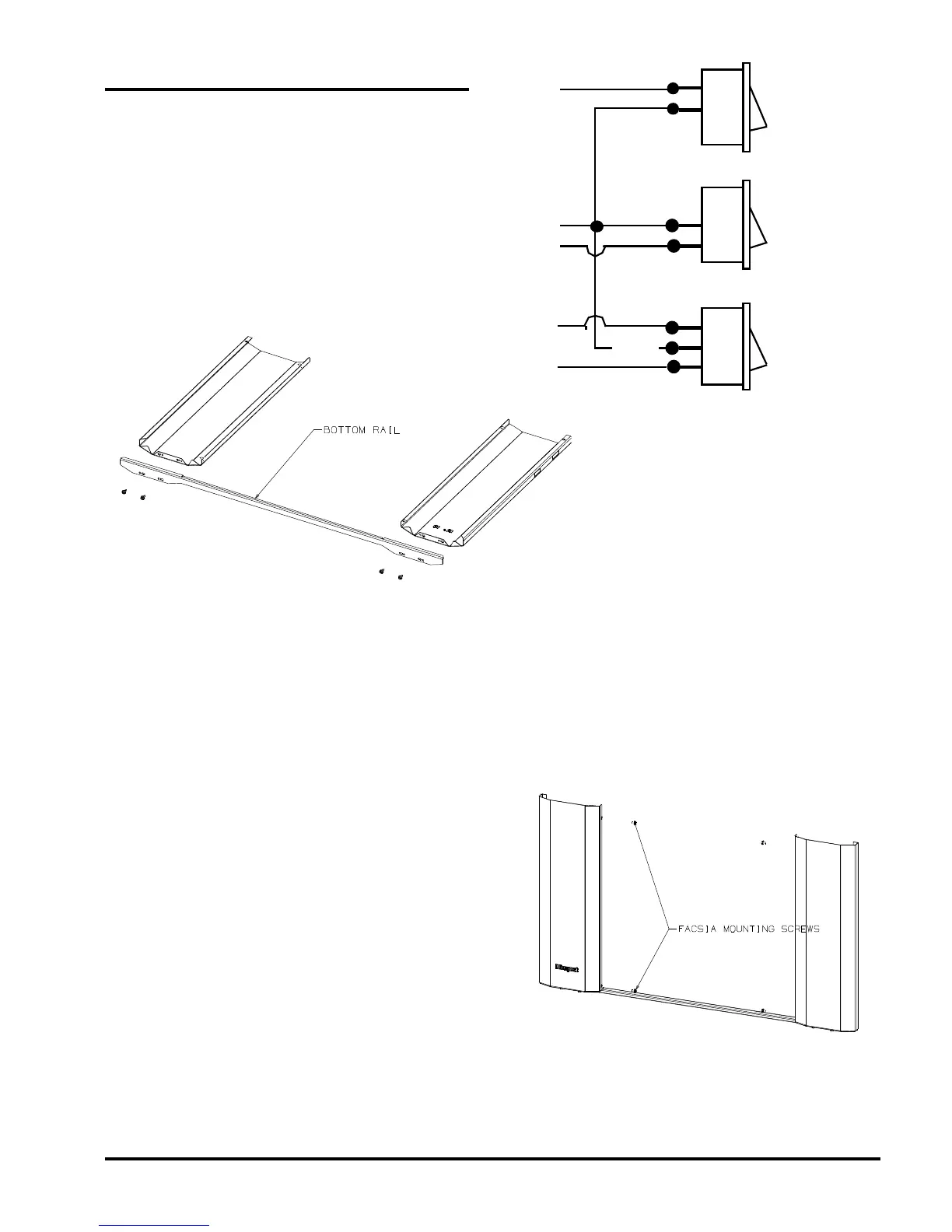
2) Align the bottom flange of each side panel with the
corresponding end of the bottom rail. Using the
self-tapping screws provided, attach the bottom rail
to the bottom flanges of the side panels. Tighten
the screws only loosely at this stage. See Fig 1.
Fig 1.
3) There are three switches supplied with the fascia.
If they have not already been assembled, insert
them in the rectangular holes in the left side of the
left fascia panel. The FAN switch (three terminals)
goes in the bottom hole either way up, the burner
HI/LO switch (two terminals with no printing on the
rocker) goes in the centre hole with the two
terminals at the bottom, while the ON/OFF switch
(two terminals) fits in the top hole with the
terminals at the top. (See Fig. 2).
4) Connect the fan wires, red, violet and black, to the
bottom fan switch, in the following positions. (See
Fig. 2).
- Black wire to centre terminal,
- Red wire to bottom terminal,
- Violet wire to top terminal.
5) Connect the burner HI/LO wires, yellow and black,
to the centre switch in the following positions. (See
Fig. 2).
- Black wire to top/centre terminal,
- Yellow wire to bottom terminal.
6) Connect the burner ON/OFF wires, blue and black,
to the top switch in the following positions. (See
Fig. 2).
- Blue wire to upper terminal,
- Black wire to lower terminal.
BLACK
BLUE
BLACK
BLACK
YELLOW
VIOLET
RED
HIGH
LOW
FAN:
HIGH
OFF
LOW
Fig 2.
7) Ensure that the wires are away from the side of the
fireplace. The power cord should be run behind the
fascia panel and out through the slot in the side of
the fascia. The rubber grommet on the power cord
should be inserted into the slot to protect the mains
lead against possible damage.
8) Offer the fascia assembly up to the case to obtain
the correct width for the side panel spacing
keeping the inside flanges of each panel on the
inner side of the mounting flange of the fireplace.
Carefully remove the assembly and tighten the
screws fastening the bottom rail to the side panels.
9) Offer the fascia assembly up to the case once
more and connect the green earth wire to the tab
on the control valve then secure the fascia through
the two holes on the inner edges of each fascia
side panel using the self tapping screws provided.
See Fig 3.
Fig 3.
10) Lower the top panel assembly into place with the
locating prongs pointing down so that they fit inside
the top edges of each side panel. Fasten the top
 Loading...