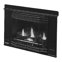
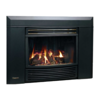
Masport P36-3 Gas Inbuilt 25
Option 2:
WALL THERMOSTAT
A wall thermostat may be installed if desired,
connect the wires as per the wiring diagram.
Use chart below to determine the maximum
wire length.
CAUTION
Do not connect millivolt
wall thermostat wires for
gas appliance to a
240V power supply.
Option 1:
REMOTE CONTROL
Use the Masport Remote Control Kit approved
for this unit. Use of other systems may void your
warranty.
The remote control kit comes with a hand held
transmitter, a receiver and a wall mounting
plate.
1) Choose a convenient location on the wall to
install the receiver and the receptacle box
(protection from extreme heat is very im-
portant). Run wires from the fireplace to
that location. Use Thermostat Wire Table.
2) Connect the two wires to the gas valve.
See diagram below.
CAUTION
Do not connect millivolt
remote control wires for
gas appliance to a
240V power supply.
3) Install alkaline batteries in both the receiver
and the transmitter. Install the receiver and
its cover in the wall. Switch the hand held
remote transmitter to "remote" mode. The
remote control is now ready for operation.
Thermostat
Wire Table
14 GA.
16 GA.
18 GA.
20 GA.
22 GA.
15.24 m
9.75 m
6.10 m
3.66 m
2.71 m
Recommended Maximum Lead
Length (Two-Wire) When Using Wall
Thermostat (CP-2 System)
Wire Size Max. Length
INSTALLATION
Refer to specific detailed instructions
supplied with each kit.
 Loading...