Masport PG36-3 Gas Inbuilt
14
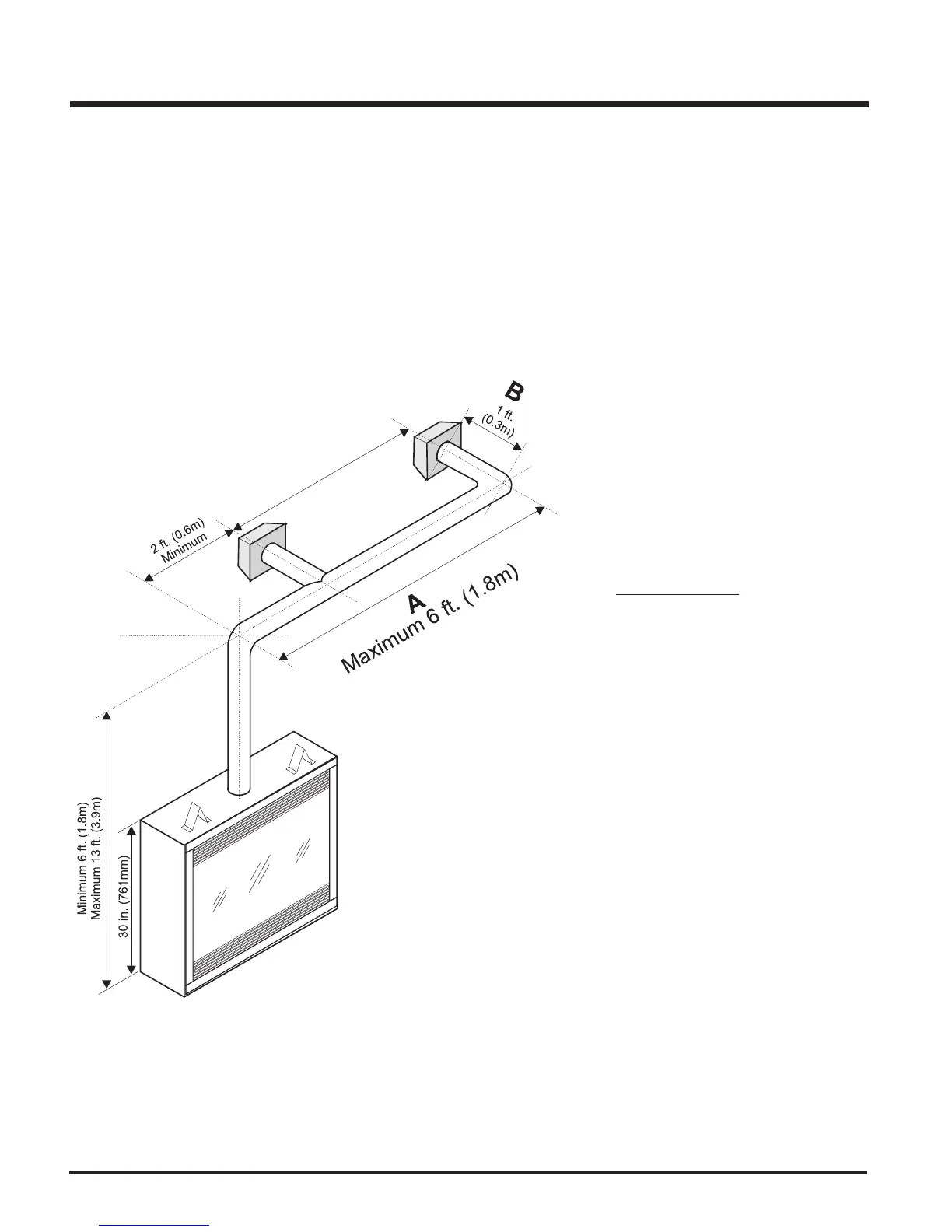
FLUEING ARRANGEMENTS - HORIZONTAL TERMINATIONS
SIMPSON DURA-VENT DIRECT FLUE GS SYSTEM and
MASPORT CO AXIAL FLUE SYSTEM (FLEX)
(LPG & NG)
The diagram below shows examples of horizontal termination arrangements using two 90
o
elbows (two 45
o
elbows equal one 90
o
elbow).
Note: 1) A maximum of two 90
o
elbows are permitted.
2) A minimum of 6 ft. (1.8m) vertical from base of unit is required if two 90
o
elbows are used.
3) Minimum distance between elbows is 2 ft. (0.6m).
4) Determine the permitted range of horizontal termination arrangements by using chart on page 12
and deducting 3 ft. (0.9m) from the maximum horizontal distance for the second 90
o
elbow.
Simpson Dura-Vent
4" (102mm) inner diameter
6-5/8" (168mm) outer diameter
• Maintain clearances to combustibles as listed on pages 6 to 8.
• Horizontal flue must be supported every 3 feet (0.9 meters).
• Firestops are required at each floor level and whenever passing through a wall.
A flue guard should be used whenever the
termination is lower than the specified minimum
or as per local codes.
If length "B" is increased, length "A" must
be decreased by a corresponding amount.
INSTALLATION
 Loading...