Masport PG36-3 Gas Inbuilt 13
INSTALLATION
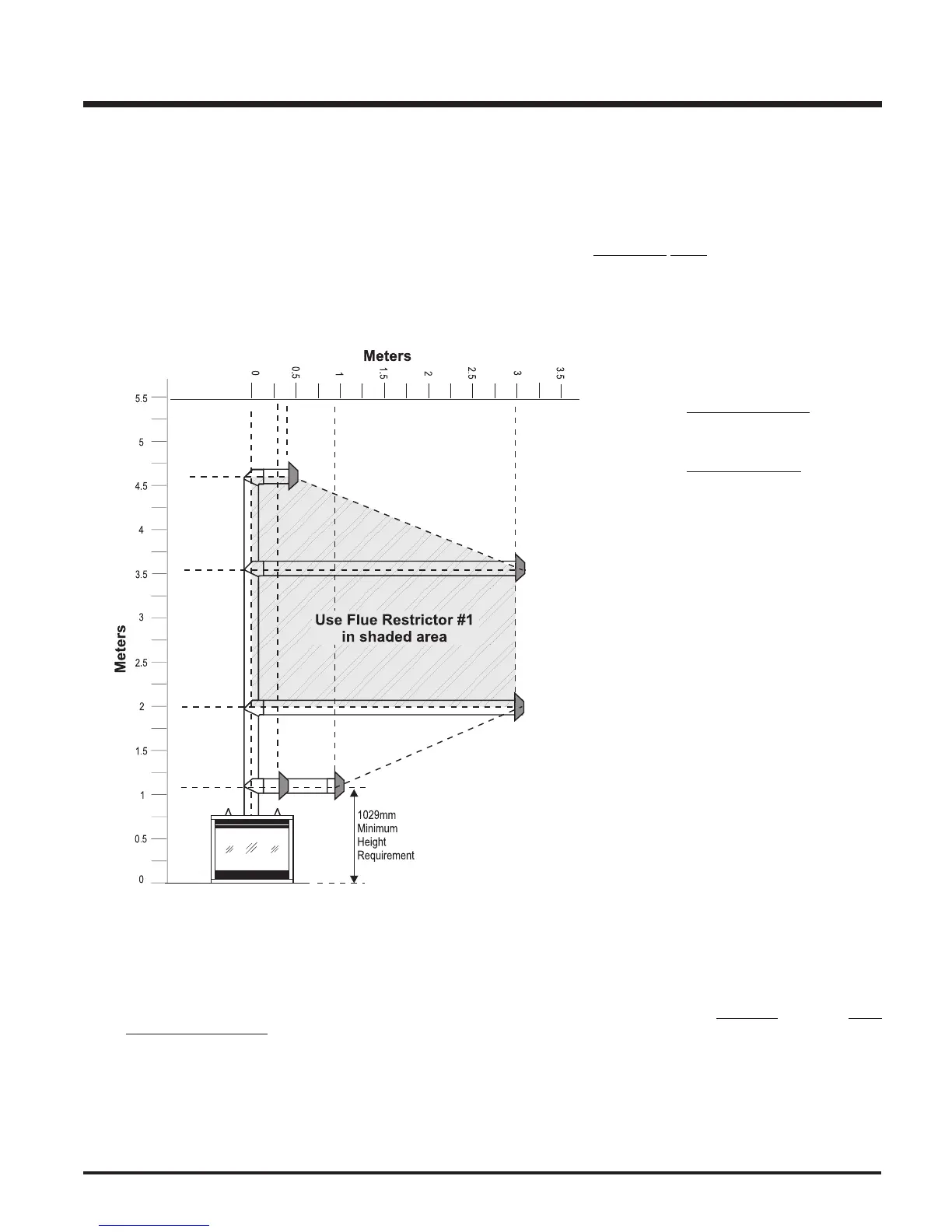
FLUEING ARRANGEMENTS - HORIZONTAL TERMINATIONS
SIMPSON DURA-VENT DIRECT FLUE GS SYSTEM and
MASPORT DIRECT FLUE SYSTEM (FLEX)
(LPG & NG)
The diagram shows all allowable combinations of vertical runs with horizontal terminations, using one 90
o
elbow (two 45
o
elbows equal one 90
o
elbow).
Note: Must use optional flue adapter (Part # 510-994) when using Simpson Dura-Vent pipe.
Simpson Dura-Vent
4" (102mm) inner diameter
6-5/8" (168mm) outer diameter
Masport Flex Vent
4" (102mm) inner diameter
6-7/8" (175mm) outer diameter
• Maintain clearances to combustibles as listed on pages 6 to 8.
• Horizontal flue must be supported every 3 feet (0.9 meters).
• Firestops are required at each floor level and whenever passing through a wall.
NOTE: If you are installing the PG36 into a Masport Mantel Kit, use the minimum horizontal flue height (centre-line of
40-1/2"(1029mm)). Remember to include the mantel base in your calculations and to maintain the 3" (76mm) clearance (using
the Mantel Heat Shield) to the underside of the mantel top.
Mantel Heat Shield MUST be used when installing the PG36-3 into the Masport Mantel Kit.
A flue guard should be used when-
ever the termination is lower than the
specified minimum or as per local
codes.
Note: Masport Co Axial Flue System
(Flex) is only approved for hor-
izontal terminations.
 Loading...