OPERATING PROCEDURES
Read all of SAFETY and this section before attempting any procedure. Pay particular attention to Notices, Cautions, Warnings and Dangers.
36
Owner’s Guide
Direction Selector Operation
To prevent loss of control, do not move the direction selector to a different position while the
vehicle is in motion. If you move the selector, the speed will immediately decrease and a warning
device activates.
Move the direction selector to FWD (forward) to move in the forward direction.
Move the direction selector to REV (reverse) to move in the reverse direction. A reverse warning buzzer activates when
the direction selector is moved to the REV (reverse) position.
The position between FWD (forward) and REV (reverse) is the
neutral position.
When you leave the vehicle, turn the key to the OFF position
and remove it from the key switch.
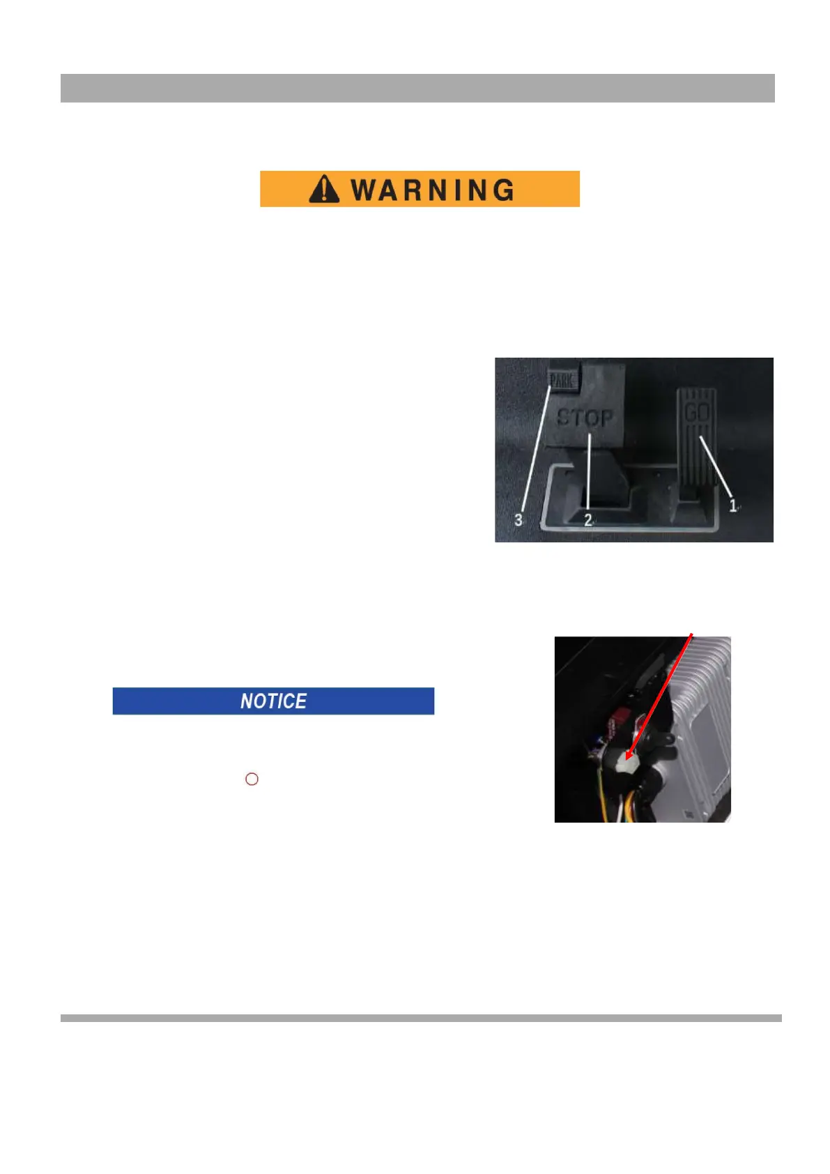
Accelerator and Brake Pedal Operation
With the key switch in the
FWD
(forward) or
REV
(reverse) position,
press the accelerator pedal (1), which starts the motor and the vehicle
moves in the direction indicated on the key switch/direction selector. This
vehicle is equipped with motor brake. When the accelerator pedal is
released, the motor will stop. To stop the vehicle quickly, press the brake
pedal
(
2
)
(Figure 2).
Horn (if equipped)
If the vehicle is equipped with a horn, the horn button (3) is located on
the driver's side of the floorboard. Pressing the button (3) will sound the
vehicle's horn (Figure 2).
Tow switch operation (If equipped)
Before starting the vehicle, please check whether the toggle
switch is in the NO state.
The car will not be able to move. Please turn off the toggle switch
when you will not start the vehicle for a long time 。
1
3
2
Figure 2 Accelerator and Brake Pedal
Operation
Curtis Programmer Port
Figure 3 Curtis Programmer
Port