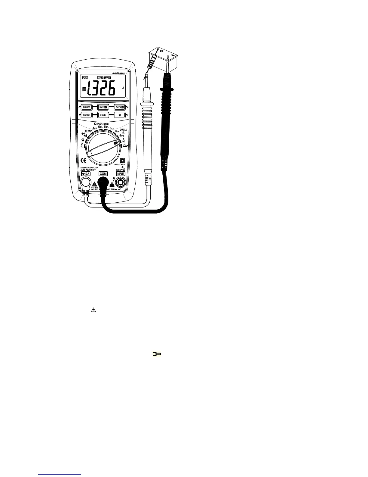
4.12.1 Connect the black test lead to the COM jack and the red test lead to the 10A jack.
4.12.2 Set the transform switch at the
A
range position.
4.12.3 Put down the "FUNC." to enter the DC measurement. Auto range or manual range can be
transformed by putting the “ RANGE ” .
4.12.4 Connect test leads in series with the load under measurement.
4.12.5 You can get reading from LCD. The polarity of red test lead will be indicated.
NOTE:
( When only the figure ‘ OL
’
is displayed, it indicates overrange situation and the higher range has to be
selected.
( When the value scale to be measured is unknown beforehand, set the range selector at the highest
position. ( “ ” means the socket of 10A jack maximum current is 10A, no fuse protection.
4.13 DC CURRENT MEASURING
(WITH CLAMP, OPTIONAL)
4.13.1 Connect the black output lead of clamp to the COM jack and the red one to the INPUT jack of the
meter.
4.13.2 Set the transform switch at the ” ” range position.
4.13.3 Put down the "FUNC." to enter the DC measurement. Auto range or manual range can be
transformed by putting the “ RANGE ” .
4.13.4 Clamp the circuit under measured.
4.13.5 You can get reading from LCD. The polarity of red output lead will be indicated.
NOTE:
( At the manual range mode, when only the figure ‘ OL
’
is displayed, it indicates overrange situation and
the higher range has to be selected.