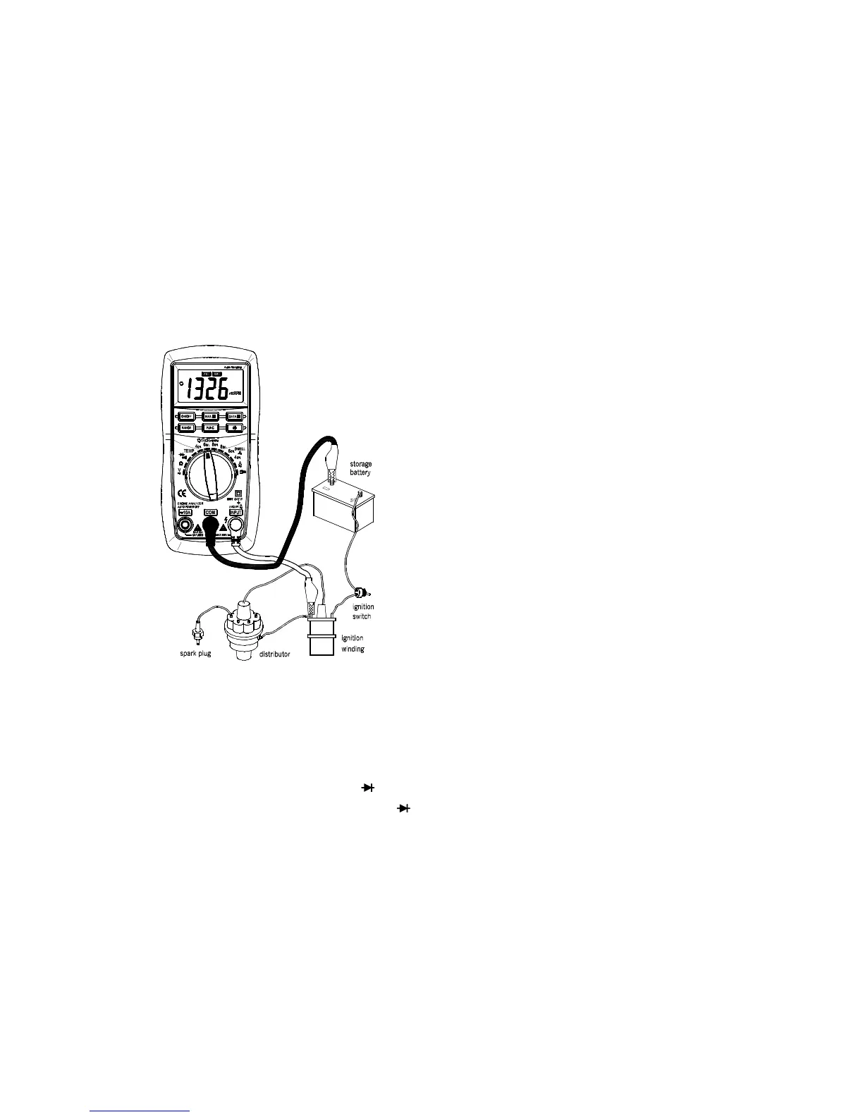
4.19.3 Connect the black test lead to the iron or the negative pole of the storage cell, and the red one to
the low voltage connection pole of the divider or the negative pole of the ignition winding for
measurement.
4.19.4 You can get reading from LCD after the engine is started.
4.20 MEASURING REV
4.20.1 Connect the black test lead to the COM jack and the red test lead to the INPUT jack.
4.20.2 Set the transform switch at the desired TACH range position according to the measured cylinder of
the engine.
4.20.3 Connect the black test lead to the iron or the negative pole of the storage cell, and the red one to
the low voltage connection pole of the divider or the negative pole of the ignition winding for
measurement.
4.20.4 You can get reading from LCD after the engine is started.
4.21 TESTING DIODE
4.21.1 Connect the black test lead to the COM jack and the red test lead to the INPUT jack. (The polarity
of red lead is “ + ” )
4.21.2 Set the transform switch at the range position.
4.21.3 put down the "FUNC." transformed at test.
4.21.4 Connect the red lead to the anode, the black lead to the cathode of the diode under testing.
4.21.5 You can get reading from LCD.
NOTE:
( The meter will show the approximate forward voltage drop of the diode.
( If the lead connection is reversed, only