INSTALLATION
EN / Mass Charger 12/60-2; 12/80-2; 24/50-2; 24/75; 24/100; 3-24/100; 48/25; 48/50 / July 2010 11
4.6 CONNECTION OF SECOND BATTERY
(3A OUTPUT)
The battery chargers 12/60-2, 12/80-2 and 24/50-2 are
standard equipped with a second charge output of 3A in
order to give a small second battery set like a starter
battery a maintenance charge. The maximum charge
current of the second output is 3A, which comes from the
main output.
• Use 2.5 to 4 mm
2
cable for connection.
• Connect the minus of the second battery to the minus
of the main battery.
• Connect the plus of the second battery to the +3A
terminal of the Mass Charger (see fig. 2 and 3).
• Integrate a 10A slow blow fuse in the plus cable.
4.7 TEMPERATURE SENSOR
The standard temperature sensor is provided with 6 m
cable and a double-sided tape for easy installation.
Determine the warmest place on the battery set and make
it clean and grease free. Remove the piece of paper from
the tape and stick the sensor on the battery. Plug the 6way
cable into a terminal at the right of the Mass Charger (see
fig. 7). For the C3 enclosure (refer to specifications) both
"RS232" and "analog" are suitable. It is not necessary to
shorten the cable. When you want to shorten it anyway
please notice the polarity of the plug and use the old
connector as an example.
4.8 VOLTAGE SENSE
To shorten the charge time substantially, the battery cable
losses can be compensated by using the sense function.
Use 0,75 mm
2
, preferably red and black wire and secure
these with fuses of 2A slow blow. Connect the wires with
the two upper terminals of the green connector at the right
side of the cabinet (see fig. 7). Pay good attention to the
polarity of the wires, red on +S and black on -S. Now
connect the other side of the wires: black on the minus of
the battery and red on the battery side of the Mass
Charger fuse.
4.9 ALARM FUNCTION
The battery charger is equipped with a potential free
contacts alarm relay, see figure 7. The alarm function has
two modes: standard (factory setting) and DC alarm mode
(continuous mode).
4.9.1 Standard alarm mode
In this mode the relay responds to all fault conditions that
the Mass Charger can detect such as: no AC input
voltage, too low DC voltage, voltage sense failure,
temperature sense failure.
4.9.2 DC alarm mode
To enable this mode a DIP switch setting needs to be
changed (switch 1 and 2 at ON). The alarm now works as
a DC alarm and responds to the battery voltage only.
Note: In the DC alarm mode the electronics stay active
permanently and drain a very small current of ± 25mA,
also when the Mass Charger is switched off.
4.10 CONNECTION OF ACCESSORIES
The battery charger is equipped with several terminals for
accessories. Cable to connect the accessories is not
delivered as a standard. Accessories can be plugged in at
all times. For C3 enclosure (refer to specifications): when
using a remote panel and the temperature sensor use the
specified plug for the panel and the other (free) one for the
temperature sensor.
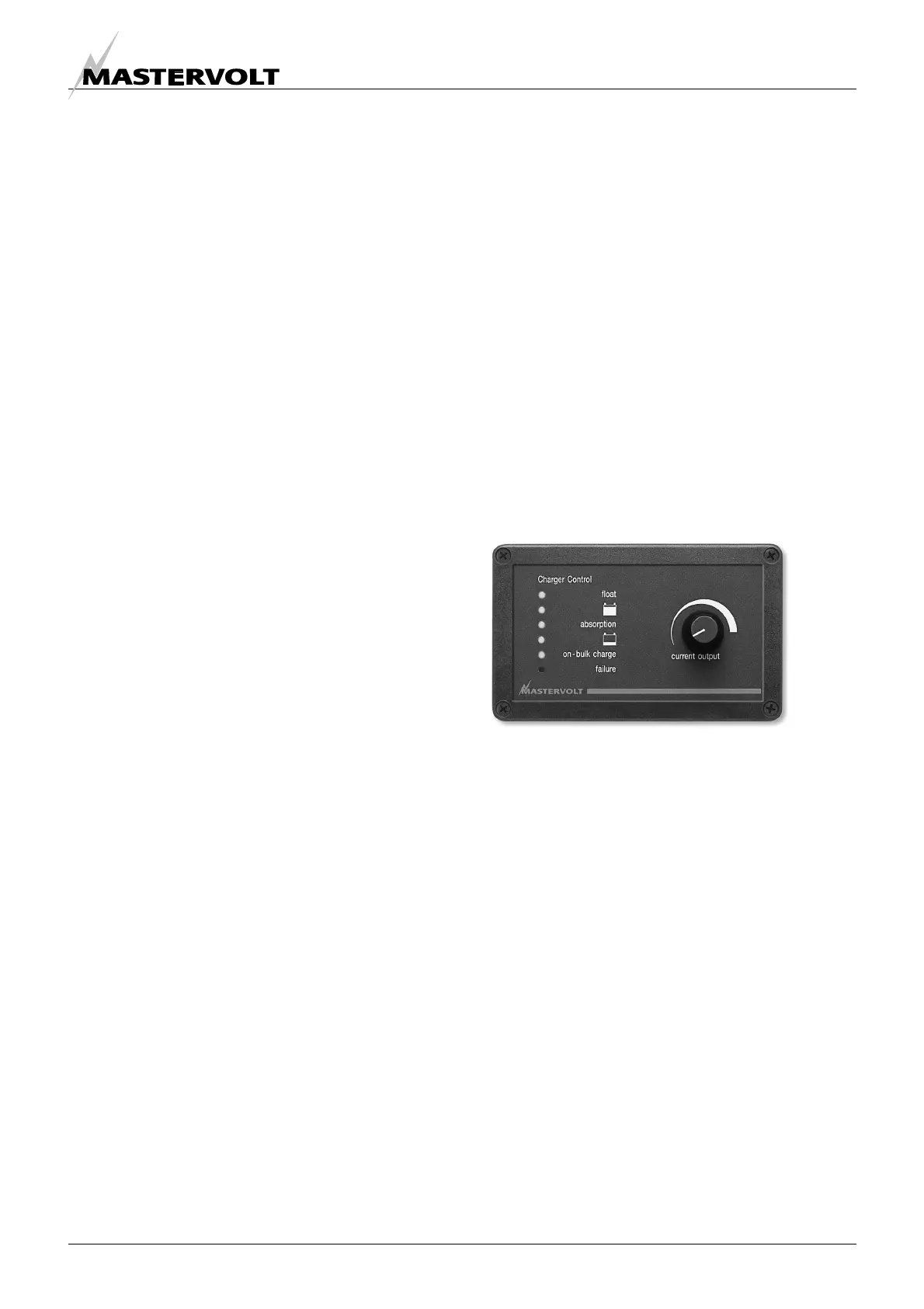
The standard remote panel must be connected with an
appropriate communication cable.
4.11 SPLITTER FOR ENCLOSURE C2
The RJ12 connector (QRS232 communication port) can
be used to connect the battery temperature sensor or the
remote panel (not included). Use a splitter to connect both
at the same time (not included).
Figure 6: Standard remote panel C3-RS,
art. no 07-04-03040