MASTERBUS
EN / Mass Charger 12/60-2; 12/80-2; 24/50-2; 24/75; 24/100; 3-24/100; 48/25; 48/50 / July 2010 17
6 MASTERBUS
6.1 WHAT IS MASTERBUS?
All devices that are suitable for MasterBus are
marked by the MasterBus symbol.
MasterBus is a fully decentralized data network for
communication between the different Mastervolt system
devices. It is CAN-bus based which has proven itself as a
reliable bus-system in automotive applications. MasterBus
is used as power management system for all connected
devices, such as the inverter, battery charger, generator
and many more. This enables communication between the
connected devices, for instance to start the generator
when the batteries are low.
MasterBus reduces complexity of electrical systems by
using UTP patch cables. All system components are
simply chained together. Therefore each device is
equipped with two MasterBus data ports. As only a few
MasterBus cables are needed, installation and material
costs are reduced importantly. New devices can be added
to the existing network easily. Consequently the
MasterBus network is highly flexible for extended system
configuration. Mastervolt also offers several interfaces like
the Modbus and NMEA interface, making even non-
MasterBus devices suitable to operate in the MasterBus
network.
For central monitoring and control of the connected
devices Mastervolt offers four different panels, from the
small Mastervision compatible 120 x 65mm LCD screen
up to the full colour MasterView System panel. All
monitoring panels can be used for monitoring, control and
configuration of all connected MasterBus equipment.
CAUTION: Never connect a non-MasterBus
device to the MasterBus network directly! This
will void warranty of all MasterBus devices
connected.
6.2 HOW TO SET UP A MASTERBUS
NETWORK
Every MasterBus device is equipped with two data ports.
When two or more devices are connected via these ports,
a local data network called the MasterBus is formed.
Keep the following rules in mind:
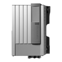
Place a terminating device on both network ends.
Terminating
device
Terminating
device
OK
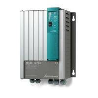
Do not make T-connections in the network.
Do not make ring networks.
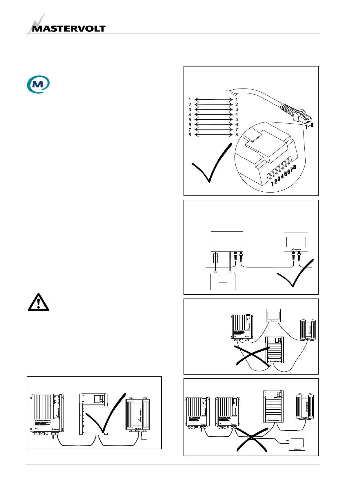
At least one device in the network must be MasterBus
powering (see specifications). As all powering devices
are galvanic isolated, multiple powering devices are
allowed.
OK
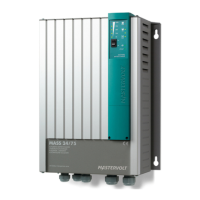
Connections between the devices are made by
standard straight UTP patch cables.
OK