INSTALLATION AND COMMISSIONING
12 August 2010 / SunMaster CS15TL/CS20TL / EN
6 INSTALLATION AND COMMISSIONING
CAUTION
Until all components have been verified to be
de-energized, at least 2 persons are required
during installation.
CAUTION!
Read chapters 2 and 4 prior to installation.
WARNING
Verify that all wiring is disconnected from any
power source during the entire installation.
Use suitable testing equipment.
CAUTION!
Short circuiting, miswiring or reverse polarity
may lead to damage to the CS15TL/CS20TL,
the cabling and/or the terminal connections.
Follow all steps of the installation instructions
in order of succession as described.
6.1 THINGS YOU NEED FOR INSTALLATION
Make sure you have all the parts you need to install the
CS15TL/CS20TL:
• 1 CS15TL/CS20TL (included)
• 1 mounting bracket (included)
• 1 AC 3-phase output plug (included)
• StringMaster CS 2-6 Pro when more than two string
inputs are needed
• 2 MasterBus terminating devices (included)
• This user’s and installation manual (included)
• M8 bolts and plugs to fix the CS15TL/CS20TL
enclosure to the wall. Use mounting materials that are
suitable for the application.
• Cabling
• Tools to fix CS15TL/CS20TL wall mounting bracket
and enclosure to the wall
• Tools to install the wiring
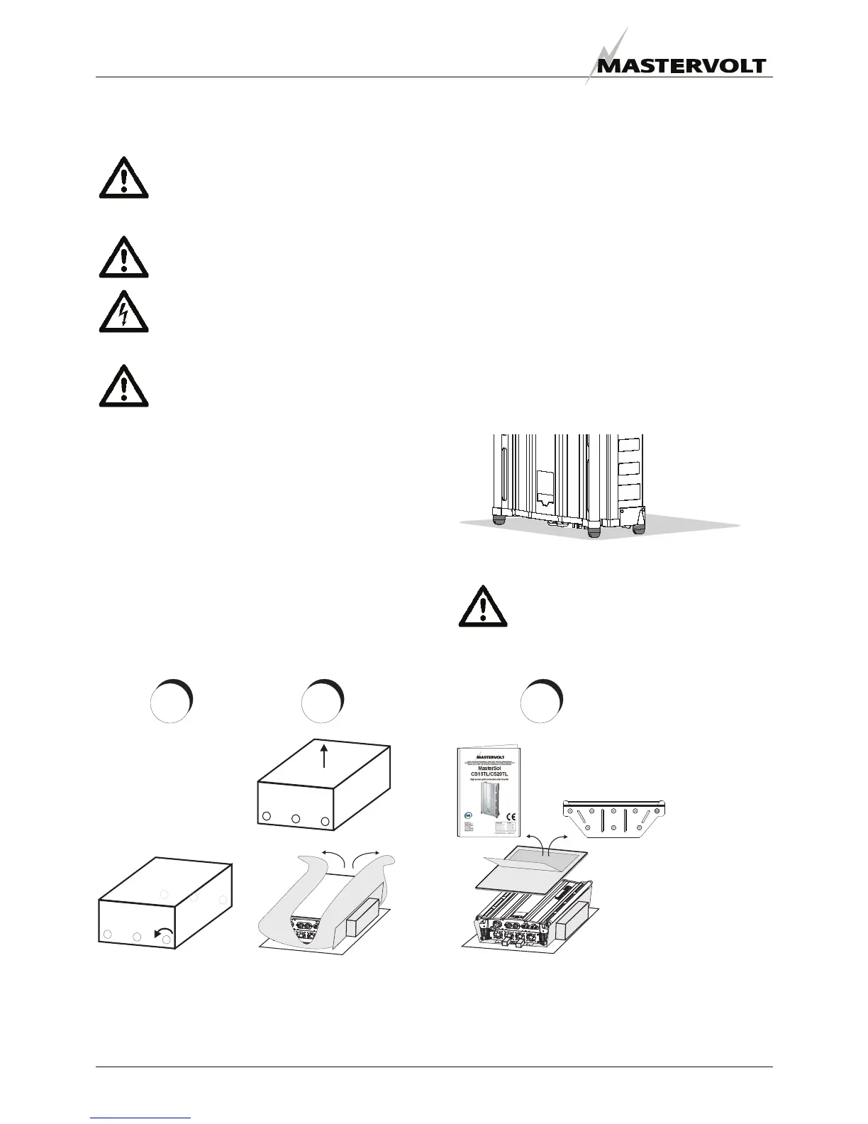
6.2 UNPACKING THE CS15TL/CS20TL
The CS15TL/CS20TL is packed in a plastic bag and
delivered in a special transport box.
1. Unscrew the 6 box screws.
2. Lift the box cover and remove the plastic bag.
3. Lift the inverter from the bottom plate.
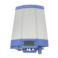
The inverter can be put on its four foot stands before
hanging it to the wall. Take care not to bend the lips.
Figure 13: foot stands
After unpacking, check the contents for possible
damage. Do not use a damaged product. If in
doubt, contact your supplier.
Figure 14: Unpacking
+
+
+
+
+
+
1 2 3
6x