USA / WHISPER 3,5 / April 2004 11
2.5.4 Battery charger
There is an extra winding in the alternator generating 6
Amp 12 V. This current is rectified on the control PCB to
charge the battery. Both the current and the voltage are
regulated.
2.5.5 Alarms and shut down
In case of malfunctioning this will be indicated by the fai-
lure light and detail will be shown on the display the
engine will be shut down. There are three functions
guarded: oil pressure, oil temperature and exhaust
temperature.
Exhaust temperature too high indicates the cooling water
to be blocked.
All alarm switches are closed when no malfunction
occurs. A contact is cut in case of an alarm. This means
that the generating set will not work when the alarm
switches are broken or there is a loose wire. The system
therefore is intrinsically safe. The panel will display
details about the alarm.
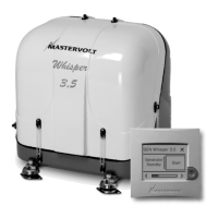
2.5.6 Control
The generating set can be operated by push buttons on
the panel on the alternator or by the remote control. By
pushing the start button the control system is activated
and will start the engine automaticly. Pushing the STOP
button will stop the engine and the electrical system will
be deactivated. Stopping the engine is executed by the
‘pull’ solenoid, at the same time the fuel valve solenoid
will shut off.
2.5.7 Remote control
All wiring connections from the remote control to the
board are made by plug in connectors.
An intermediate communication cable is in the standard
supply. If necessary an optional longer 8 wire twisted
cable can be connected if the standard length does not
suit the required distance. Numerous remote control units
can be put in parallel by using the connectors on the
back of the units. (Refer to installation instructions)
2.5.8 Hour counter
The remote control offers several timer functions and
helps to schedule maintenance.
2.5.9 Load indicator
On the remote control the load will be indicated on the
display and by the LEDbar. The load is measured by a
current transformer on the alternator.
2.5.10 Fuel specification
The engine must only be used with diesel fuel oil which
conforms to the standards for use in modern diesel en-
gines. Fuel free from water and contaminants is of the ut-
most importance.
2.5.11 Oil information
1Specification:
The oil must be suitable for oil changes as specified
in the maintenance chapter. The Kubota engine must
be run on heavy duty lubricating oil meeting the requi-
rements of API class CC or CD.
It is very important to use the correct oil
specification. Very often local oil suppliers
recommend a higher class, because they
assume that a higher class is allowed. This
is not the case. One should not follow
these recommendations.
Using the wrong specification will cause
high oil consumption.
2 Oil viscosity:
We recommend a multigrade oil 15W40.
3 Oil capacity:
Excluding the oil cooler the content of the crankcase
is 1,3 U.S. qts ≈ 1,3 l. Including the oil cooler it is 1,5
U.S. qts ≈1,5 l.
Do not overfill with lubricating oil as this may have a
detrimental effect on engine performance and cause
damage.
4 Oil pressure
• Minimum at idle 49 Kpa (0,5 kgf/cm2-7psi).
• Normal at 3600 rpm between 147 and 490 Kpa
(1,5 up to 5 kgf/cm2- 21 up to 71 psi).
• Minimum at 3600 rpm 98 Kpa (1,0 kgf/cm2/
14 psi).
INFORMATION