USA / WHISPER 3,5 / April 2004 9
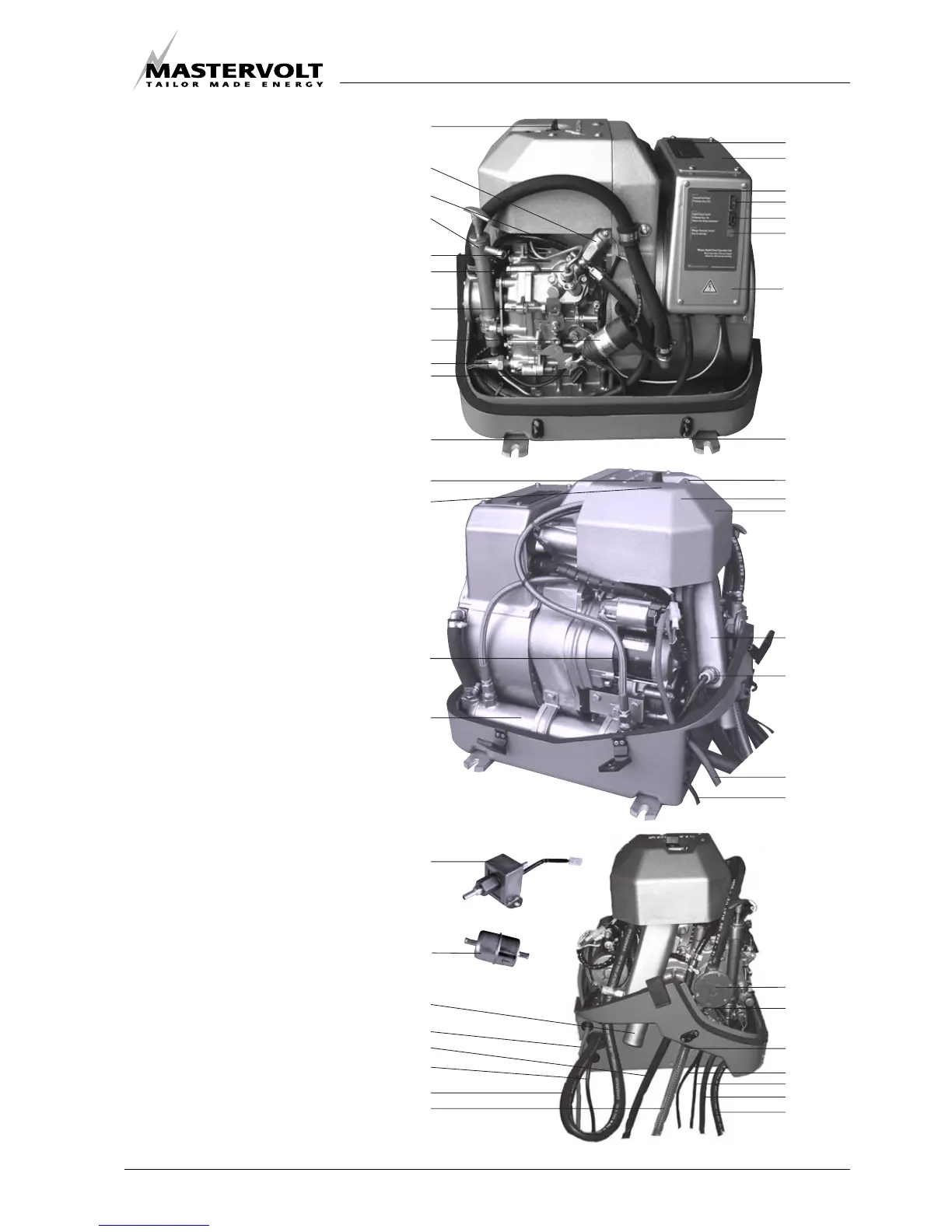
Fig. 2: Overview Whisper 3500.
1 Air inlet;
2Starter motor;
3 Battery connection (positive);
4 Battery connection (negative);
5 AC 230 V wiring;
6 AC 230 V output connection box;
7 Fuel filter;
8 Fuel pipe inlet;
9 Fuel pipe return;
10 Bypass hose air vent;
11 Cooling water in;
12 Exhaust manifold (water cooled);
13 Thermo-switch exhaust;
14 Glow plug;
15 Injector;
16 Valve cover;
17 Decompression handle;
18 Oil filler cap;
19 Solenoid fuel valve;
20 Electric fuel lift pump;
21 Cooling water pump;
22 Oil pressure pump;
23 Fuel pressure pump
24 Oil pressure switch;
25 Oil sump pump;
26 Exhaust connection;
27 Fuel return;
28 Oil filler cap/ oil level indicator;
29 Control panel;
30 Capacitor;
31 Fuse 1;
32 Fuse 2;
33 Remote control cable;
34 Stop solenoid;
35 Oilstrainer cover;
36 Start button;
37 Digital Diesel Control unit;
38 RPM set screw;
39 Oil temp switch;
40 Plug screw;
41 Heat exchanger.
2.4 COMPONENTS
2.4.1 Main components to identify
INFORMATION