USA / WHISPER 3,5 / April 2004 19
MAINTENANCE
4 MAINTENANCE
4.1 ALTERNATOR
The alternator does not require any maintenance. Perio-
dic inspection and cleaning is recommended, depending
on environmental conditions.
However when the alternator has been idle for a long pe-
riod attention to winding condition is recommended.
The condition of windings can be assessed by measure-
ment of insulation resistance to earth.
The CAPACITOR should be disconnected during this
test. A 500V ‘Megger’ or similar instrument should be
used. The insulation resistance to earth of all windings
should be in excess of 1.0 MOhm. Should the insulation
resistance be less than this value, drying out the genera-
tor windings is essential. Drying out can be carried out by
direct warm air from a fan heater or similar apparatus into
the generator air inlets or outlets.
All bearings are greased for life and not regreasable.
4.2 ENGINE
4.2.1 Preliminary instructions
All regular maintenance can be executed when the en-
closure is open. For repairs we recommend to take out
the generating set to a workshop. The enclosure can be
completely removed by taking out the bolts form the
aluminium bars below the bottom of the capsule.
When oil and dirt have gathered in the enclosure measu-
res have to be taken to avoid spilling oil and polluting the
environment.
The first service on the engine should be carried out after
25 hours of its life. This also applies after a major over-
haul. In the first 25 hours the engine should receive spe-
cial attention:
Long periods of light or no load running in the first 25
hours may lead to cylinder glazing and high oil consump-
tion.
For the same reason it is of the greatest
importance to use the right oil specifica-
tion.
The first time starting up or after running out of fuel it
could be necessary to prime the fuel system.
4.2.2 Bleeding fuel lines
Ensure there is sufficient fuel. The system is self
bleeding. The first time starting up or after running out of
fuel it could be necessary to prime the fuel system. Push
“start” and monitor the display. Extend fuel pumping time
by pushing “stop” when the display indicates “preheat”
and push “start“ again.
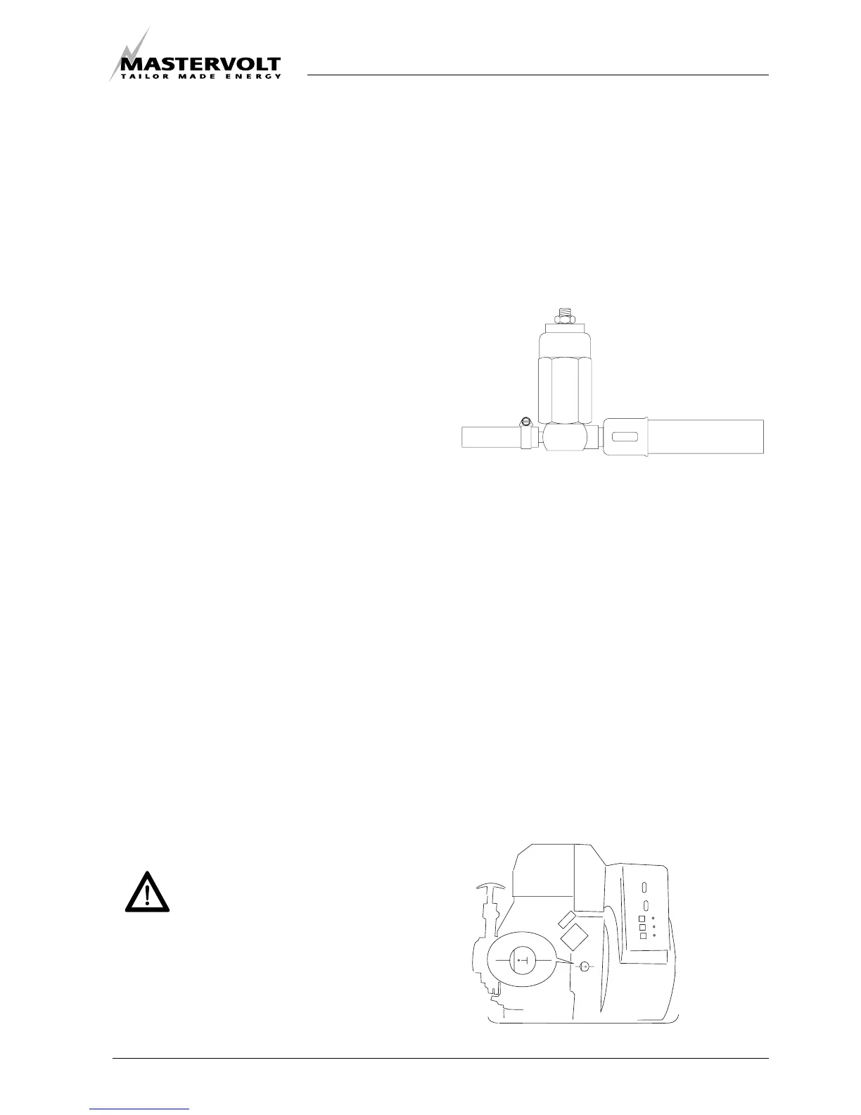
4.2.3 Valve clearance
Tightening torques, refer to § 5.4.2.
When the engine is in cold condition both valves should
have a clearance between 0,0055 and 0,007 inches
(0.14 and 0.18 mm). The adjustment has to be done at
T.D.C. of the compression stroke. Using a pocket light
one can check the position of the flywheel (refer to
picture 12). By using the decompression handle one can
crank the engine easily with a screwdriver to put the
marks in line. Confirm that the valves do not move up or
down when the crankshaft is turned about 20 degrees in
normal and reverse direction of rotation. If the rocker
arms move the piston is on the T.D.C. of the intake or
exhauststroke. In such a case turn the crankshaft 360° in
the direction of engine rotation again. The piston is now
at T.D.C. of the compression stroke. After readjustment
one should crank the engine for 20 rotations and check
the valves again.
Fig. 11: Self bleeding fuel lines.
Fig. 12: Valve clearance.