66
Appendix B: Technical reference
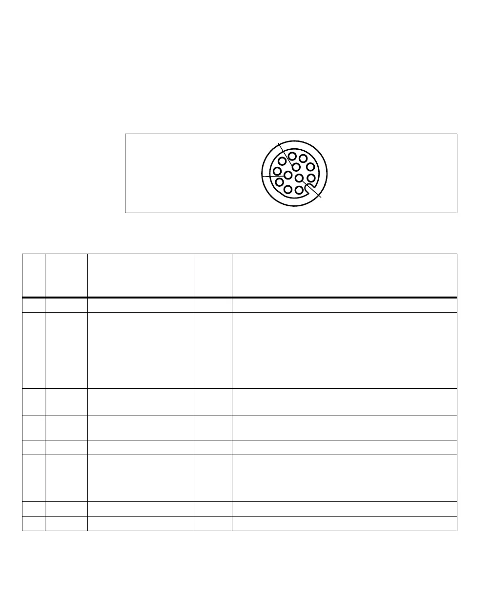
Digital I/O and power connector
The digital I/O and power connector is an M12 12-pin (female) connector that
transmits and receives digital I/O signals, provides an analog intensity (dimming)
control signal for an inline control system lighting controller, and provides power
to your Matrox Iris GTX.
The pinout for the digital I/O and power connector is as follows:
o
Pin Wire color Hardware signal name DA name
for
auxiliary
signal
Description
1 Brown AUX_OPTOIND_OUT_COMMON N/A Opto-isolated industrial auxiliary signal (output) common.
2 Blue AUX_AREF_OUT7 N/A 0-10 VDC Analog intensity control signal (output). Note that this signal
uses the - VDC for reference.
Supported function: a 0-10 VDC analog intensity (dimming) control
signal that can be received by typical lighting controllers (such as, an
Advanced Illumination inline control system (ICS3), Smart Vision Lights
Brick light, or other similar devices). This pin used to be referred to as the
Analog reference voltage signal.
3 White AUX_OPTOIND_OUT2 AUX IO2 Opto-isolated industrial auxiliary signal 2 (output).
Supported function: user-bit 2 (output 3 of 3).
4 Green + VDC N/A Positive pin of the power provided to your Matrox Iris GTX. This pin must
be connected to a + 24 V +/- 10% power supply.
5 Pink AUX(TRIG)_OPTOIND_IN3 AUX IO3 Opto-isolated industrial auxiliary signal 3 (input).
6 Yellow AUX_OPTOIND_IN_COMMON N/A Opto-isolated industrial auxiliary signal (input) common.
Supported function: Whether you should connect this pin to an electrical
return path or a voltage source depends on whether the third party device
is sourcing or sinking the current, respectively.
7 Black AUX_OPTOIND_IN5 AUX IO5 Opto-isolated industrial auxiliary signal 5 (input).
8 Grey AUX_OPTOIND_IN6 AUX IO6 Opto-isolated industrial auxiliary signal 6 (input).