Matrox Iris GTX connectors 67
To interface with this connector, you can use either the cable that comes with the
starter kit, M12-CBL-PWR/3, or you can build your own. To build your own
digital I/O and power cable, parts can be purchased from:
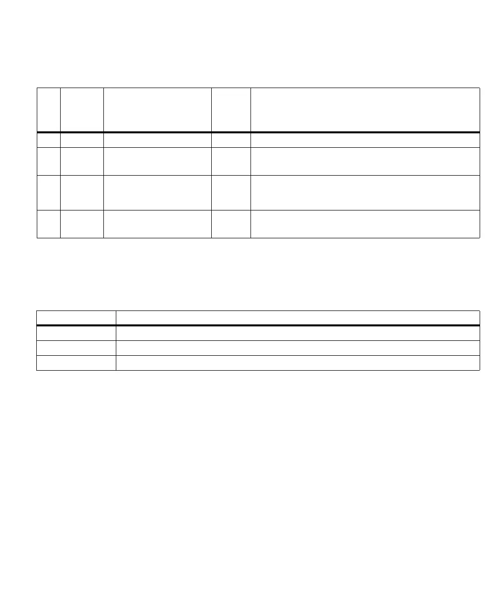
Pin Wire color Hardware signal name DA name
for
auxiliary
signal
Description
9 Red AUX_OPTOIND_IN4 AUX IO4 Opto-isolated industrial auxiliary signal 4 (input).
10 Violet AUX_OPTOIND_OUT0 AUX IO0 Opto-isolated industrial auxiliary signal 0 (output).
Supported function: user-bit 0 (output 1 of 3).
11 Gray-Pink - VDC N/A Negative pin of the power provided to your Matrox Iris GTX. This pin must
be connected to the electrical return path of the + 24 V +/- 10% power
supply connected to the +VDC pin.
12 Red-Blue AUX_OPTOIND_OUT1 AUX IO1 Opto-isolated industrial auxiliary signal 1 (output).
Supported function: user-bit 1 (output 2 of 3).
Cable information
Manufacture Phoenix Contact GmbH & Co. KG
Part number: SAC-12P- MS/3,0-PVC SCO Order No:1554788
Description: Sensor/actuator cable, 12-pos., black PVC, straight M12 SPEEDCON plug on free conductor end, length: 3.0 m