INTRODUCTION1 - 3
DSE-17 www.maxcess.euMI 1064 1 C
– The nearest negative contrast is assigned to the output
function "Edge 2."
– The remaining contrasts are assigned in the same manner to
output functions "Edge 3" and "Edge 4."
Important information:
– The distance between two material webs must be greater
than 40mm.
– If a material web less than 40mm in width is within the
sensor field of view, a configuration designed especially for
narrow webs must be used. Otherwise invalid values will be
generated.
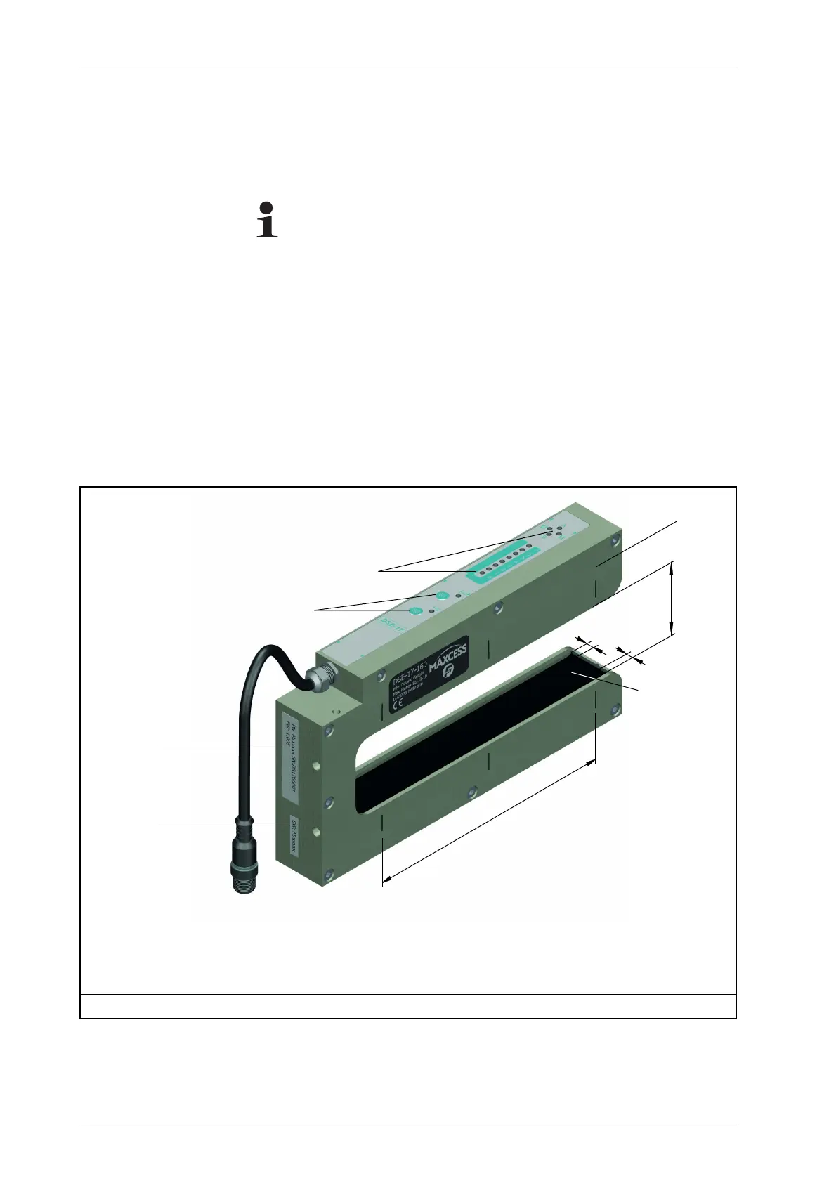
The configuration number (item 5 in
Figure 1.1
) identifies the
user-specific assignment of the signals. For further information
refer to the configuration drawing in the system documentation.
1 Sensor field of view
2 Control elements
3Displays
4 Part, serial and firmware numbers
5 Configuration number
6Protection pane
7 Upper side of the sensor fork
8Fork opening
9 Field of view restriction - 6.8mm on each side
Figure 1.1: DSE-17 digital infrared sensor
1
2
3
4
6
7
5
8
9
9