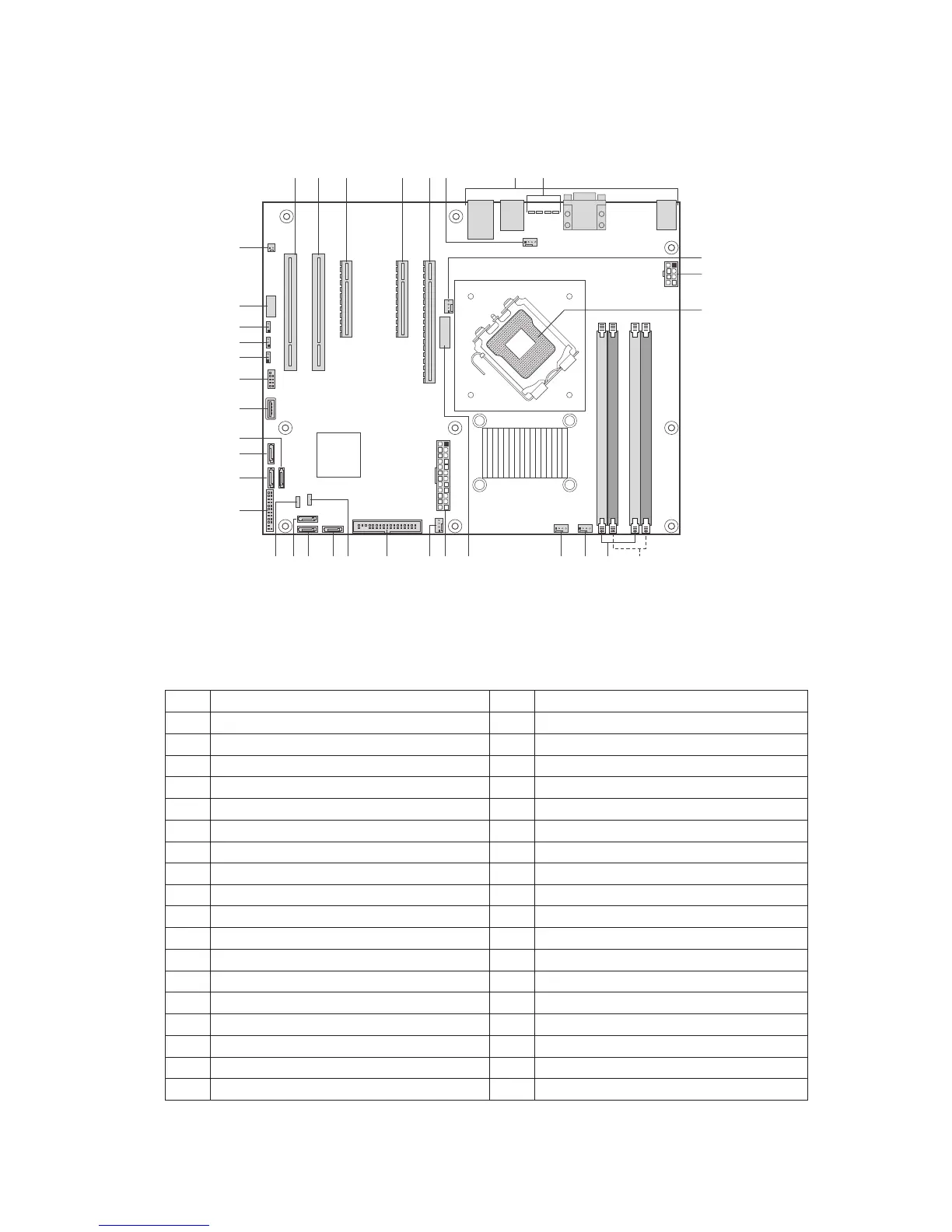
Connector and Header Locations
Figure 2 shows the approximate location of the major components on board.
Figure 2. Board Connector and Component Locations
Table 2. Board Connectors and Components
Label Description Label Description
A. PCI (5V/32bit/33MHz) Slot 1 S. Floppy Connector
B. PCI (5V/32bit/33MHz) Slot 2 T. HSBP
C. PCI Express x8 U. SATA 0
D. PCI Express x8 V. SATA1
E. PCI Express x16 W. SATA 2
F. System Fan 1 Connector X. IPMB
G. Back Panel Connectors Y. Front Panel Header
H. Diagnostic LEDs Z. SATA 4
I. Processor Fan 1 Connector AA. SATA 5
J. 2x4 Aux Power Connector BB. SATA 3
K. Processor Socket CC. Internal USB
L. Channel 2 DIMM Sockets DD. External USB
M. Channel 1 DIMM Sockets EE. CMOS Clear Jumper
N. System Fan 4 Connector FF. Password Clear Jumper
O. System Fan 3 Connector GG. BIOS Recovery Jumper
P. Battery HH. Serial Port
Q. Main Power Connector II. Chassis Intrusion Header
R. System Fan 2 Connector