PH50B
20195 South Diamond Lake Road, STE 100
Rogers, MN 55374
20
www.maximmfg.com
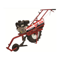
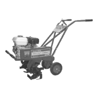
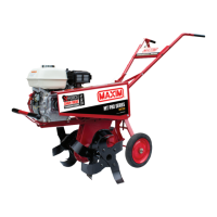
3.2 General Information
Engine Briggs & Stratton, 127cc
Gear Reduction 6:1
Handles 1” – 14 Gauge Steel
Tractor Lug 6-12 Super Sure Grip
Included Accessories 7” Turn Shovel, 12” Sweep, 8” Furrower
Tractor Lug 6-12 Super Sure Grip
Dimensions (L x W x H) 77” x 26” x 44”
Shipping weight 160 lbs.
4 ASSEMBLY
Prior to assembling your plow, make sure that you have a clear work space and that there are no
missing parts.
1. Remove the plow from the box. Do not attempt to lift the plow from the box. After
opening the top, cut all four sides of the box and lay the sides flat on the floor of working
space. Be VERY CAREFUL UNIT DOES NOT FALL OVER.
2. Stand unit securely on kick stand.
3. Take out all unassembled parts, parts bag, and protective packing and owner’s manuals.
4.1 Handle Assembly
1. Assemble handles to the front of the Plow Hoss (flat ends to the outside of frame) using
two 5/16 x 1” bolt and lock nuts. Insert bolts with heads inside frame. Tighten to snug fit.
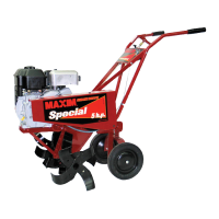
2. Fasten rear handle braces in desired adjusting hole, for operator height, to the frame. For
the left side mount, start by removing the bolt from the rear belt cover bracket and use it
to mount the handle brace and bracket using the same bolt. For right handle brace, insert
one 5/16 x 1” bolt in the same hole used for adjustment as the left brace and tighten to a
snug fit.
3. Mount left handle brace and clutch cable guide to top hole of left handle, as shown
below, using one 5/16 x 1” bolt.