Setup
Connections
EPOS4 50/5 Hardware Reference
CCMC | 2022-04 | rel10445
3-49
3.3.11 CAN 1 (X11) & CAN 2 (X12)
The EPOS4 is specially designed being commanded and controlled via a Controller Area Network (CAN), a
highly efficient data bus very common in all fields of automation and motion control. It is preferably used as
a slave node in the CANopen network.
For the CAN configuration “DIP Switch Configuration (SW1)” on page 3-56.
Figure 3-39 CAN 1 connector X11/CAN 2 connector X12
Table 3-54 CAN 1 connector X11/CAN 2 connector X12 – Pin assignment
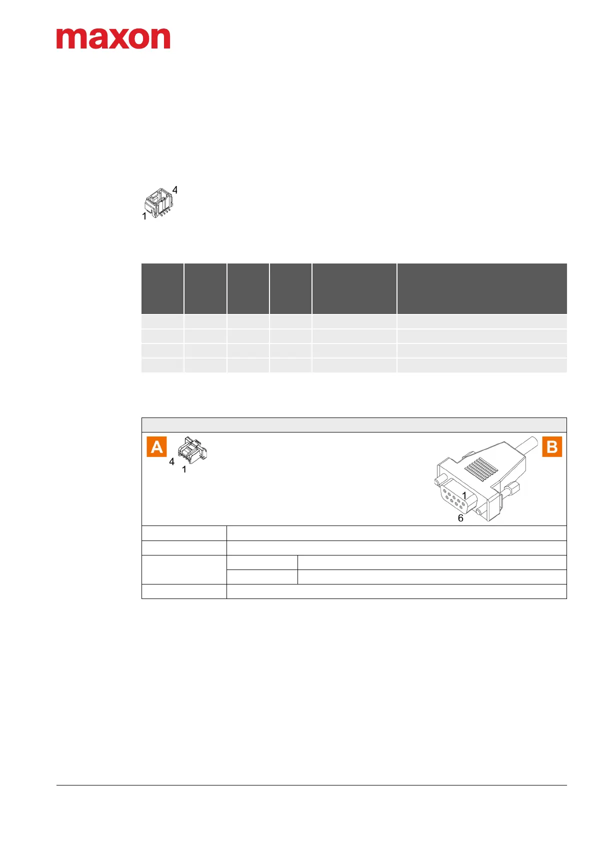
Table 3-55 CAN-COM Cable
Continued on next page.
X11
X12
Head A
Prefab
Cable
520857
Head B
520858
Head B
Signal Description
Pin Color Pin Pin
1 white 7 1 CAN high CAN high bus line
2 brown 2 2 CAN low CAN low bus line
3 green 3 3 GND Ground
4 Shield 5 4 Shield Cable shield
CAN-COM Cable (520857)
Cross-section
2 x 2 x 0.14 mm
2
, twisted pair, shielded
Length 3 m
Head A
Plug Molex CLIK-Mate, single row, 4 poles (502578-0400)
Contacts Molex CLIK-Mate crimp terminals (502579)
Head B Female D-Sub connector DIN 41652, 9 poles, with mounting screws
 Loading...