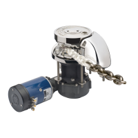
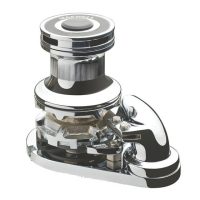
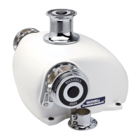
RC12 Windlass
Wiring Instructions
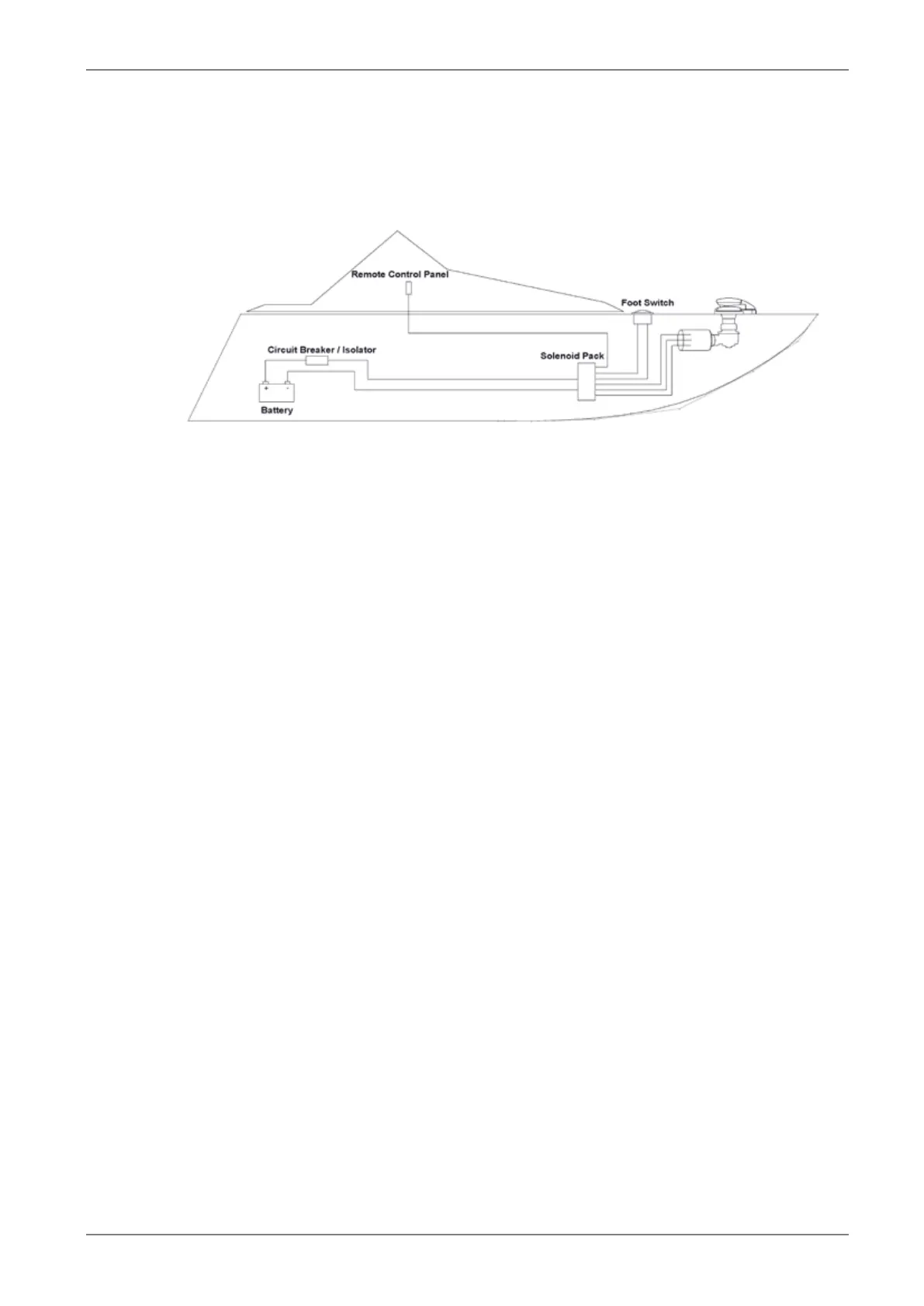
Electrical component layout
Figure 5 - Electrical component layout
Solenoid pack
The solenoid pack should be located in a dry area (not in the rope/chain locker) close to the
windlass.
Circuit breaker/isolator panel
This unit provides limited protection for the motor and full protection for the power supply cables. It
also provides the means to isolate the system from the battery.
Position the circuit breaker/isolator no further than 1.8 m (6 ft) away from the battery in an
accessible and dry location.
This equipment or equivalent is mandatory to meet USCG requirements.
Remote control panel
The remote control panel should be mounted in a convenient location (such as the bridge, helm or
cockpit) so that the operator can see the windlass. Mount and seal the panel so that the terminals
project into a dry area.
Optional footswitches
For safe operation, the footswitches must be at least 500 mm (20") from the windlass.
The below-deck part of the footswitch must be in a dry environment and installed per instructions.
The arrows on the footswitches should be arranged to indicate the direction of operation.